The upsurge in automation within the Industrial sector has given rise to an unforeseen interaction between human operators and automated machinery. The onus is on engineers to implement appropriate and often overlapping safety measures to avoid consequences that vary from interruptions in production to injury or even a casualty. Safe environment in a factory is a multi-faceted issue that requires engrossment from all levels of the organization and should commence from the factory floor up to the management. Ideally, a safe factory is designed from the ground up, but many plants predate the widespread adoption of automation which includes the use of the Industrial Internet of Things (IIoT), Artificial Intelligence, and other industry 4.0 technologies. Functional safety has become an integral part of developers as it averts systematic failures, anticipates its effect or mitigates future risk, and has transformed the way engineers think about designing systems.
Usually, product development and process operations engineers perform a ‘Failure Mode and Effects Analysis (FMEA)’ to analyze potential failure risk in the system in terms of severity and probability. This is based on experience with similar products or processes where the purpose is to exclude identified faults from the system, thereon minimizing the risk involved. FMEA defines the term failure mode to identify potential or actual defects in the design or process, focusing on those that affect the end-user, whereas failure effect is the result of a failure mode of a product or system feature as perceived by the operator.
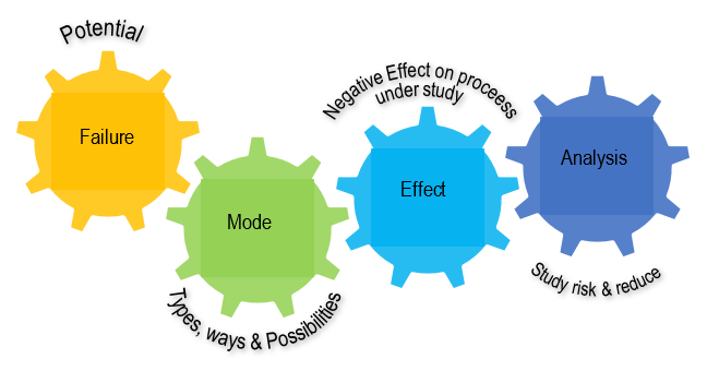
Figure 1. What is FMEA?
The impact of a fault can be explained in terms of what the end-user can perceive and experience. Investigating the outcome of the identified fault is called impact analysis. FMEA prioritizes faults according to their severity, frequency, and detectability. FMEA also contains documentation on the current state of knowledge about disability risk and seeks to mitigate risk at all levels. As a result, priority actions are taken to prevent the failure or at least reduce its severity and the likelihood of occurrence. This, in turn, assists in defining and selecting repair actions that alleviate the impact and consequences of a failure. In FMEA, the following 7-step approach as depicted in Figure 2 can be used from the initial design and conceptual stages to the development and testing processes, as well as for continuous operational process control throughout the product or system life cycle.
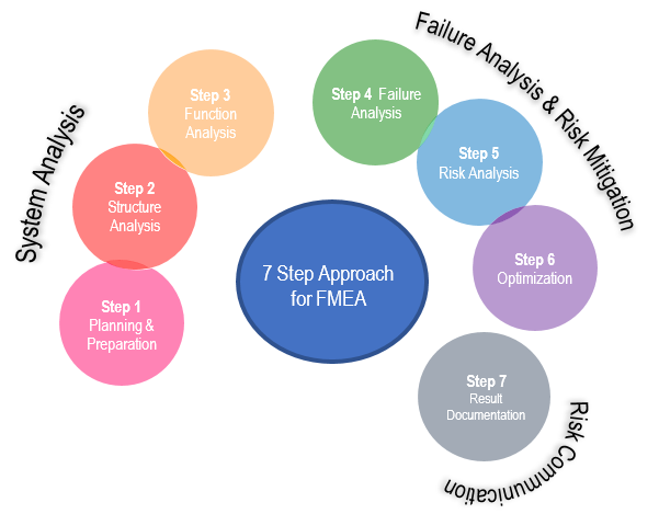
Figure 2. FMEA Approach (Source: AIAG & VDA FMEA Handbook 2019)
An adaptation of the Functional Safety standard IEC 61508 and applicable throughout the lifecycle of autonomous systems, as its basis. As shown in Figure 3, broadly functional safety system development proceeds in various development verification phases: the introduction/concept phase, which includes specification review; the detailed design/trial phase which includes functional evaluation; and the main certification phase, which includes third-party inspection and verification. The whole process has technical requirements and processes that are absent in conventional development. Keeping the above constraints in view, Renesas' solutions for functional safety development ease customer’s challenges in Figure 4.
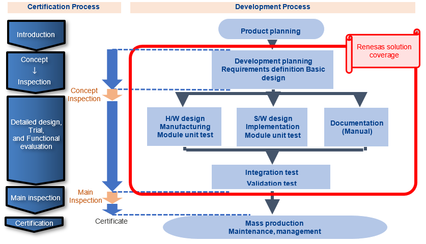
Figure 3. Functional safety system development phases
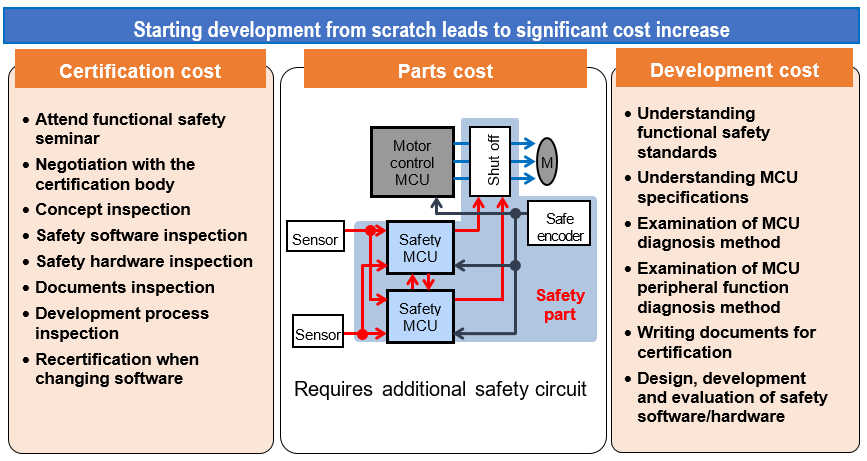
Figure 4. Technical challenges in attaining functional safety standards certification
The first step in developing a functional safety system is the concept phase, when specifications are reviewed, which also requires a variety of documentation. Developers without any certification experience will have to go through the process of filling out each entry and description, which is a time-consuming and costly step.
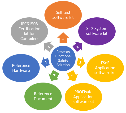
Figure 5. Renesas Functional Safety Solutions Environment
Figure 5 displays seven solution building blocks offered by Renesas Electronics to support functional safety system development for the IEC61508 standard.
Functional safety systems require fault diagnosis to avoid hardware failures that can prevent the safety functions from operating correctly. In addition to detecting individual device failures (permanent failure), fault diagnosis must also detect soft-error malfunctions (transient failure) caused by radiation, noise, and so on during operation and immediately shift to safe operation, such as stopping motors if an abnormality occurs. Fault diagnosis for individual devices requires analysis of each one's failure mode, an examination of fault detection methods to detect those modes, and defining the fault detection rate (diagnostic rate) based on that detection method. It is also necessary to detect soft errors using systematic functions such as monitoring program execution sequences, or inter-comparison using redundant MCUs for safety.
- Our ‘Self-Test Software Kit’ offers a self-diagnostic program to detect errors based on General Purpose MCUs, which achieves a diagnostic rate of 90% for permanent failure, satisfying the SIL 3 level required for IEC61508 standards.
- The ‘SIL 3 System Software Kit’ comes preloaded with software for cross monitoring, partitioning function between safety and non-safety application to enable the coexistence of safety software and non-safety software, capable of synchronous process on two MCUs with multiple clock sources, and other functions to implement redundant systems. The solution can be used as-is by developers as it is already SIL3 certified under IEC61508.
Applying these solutions allows developers to build a redundant functional safety system by simply configuring the Self-Test Software and SIL3 System Software Kit, liberating them from tedious Safety MCU diagnostics and control section development for redundant Safety System. - In addition, the Functional Safety Network protocols are necessary as the systems connected and controlled via industrial network. The FSoE Application Software Kit and PROFIsafe Application Software Kit are the certified kit to perform safety protocol in each slave devices.
Furthermore, specific hardware is required to implement redundant system, such as communication means for cross monitoring between two safety MCUs, power supply isolation and monitoring, and input/output circuit diagnostics. We offer two reference solution for customers. - Reference Documents include specific examples of the documents required in the concept phase based on the example of implementing a safety system for a motor drive. Using them as templates, the developer can modify each entry as needed to fit use specifications, so that only the necessary information is included. Determining whether the hardware/software being designed has reached the target safety level requires defining the hardware failure rate, diagnosis methods, and the diagnosis rate, calculating various parameters using complex formulas based on reliability theory, and showing whether they meet standard values for the target safety level. Reference Documents contain completed samples of all the verification documents, with detailed explanations of calculation methods for all the parameters and the formulas offered in Excel format. With these tools, even first-time developers can proceed with assurance by simply entering in data like failure and diagnostic rates. As methods related to peripheral Safety MCU functions vary depending on the use case, the reference documents describe different diagnosis methods according to diverse use cases.
- In terms of Reference Hardware, Renesas offers reference data, including power circuits for redundant Safety MCU. Another advantage of using redundant configuration is that by exchanging processing data between each side, it is possible to confirm normal operation without using any special diagnostic hardware. These hardware configurations and diagnostic techniques series are described in Solution 4: Reference Documents.
- Finally, the compilers used for this software must be proven to be valid when developing functional safety systems. Renesas also offers Certification kit for CC-RX, an IEC61508 SIL3 certified kit to be used together with the compiler. IAR Systems also provides SIL 3 certified compilers.
Also summarized in Figure 6, Renesas offers comprehensive solution building blocks that enable an accelerated functional safety system development. Our solution package includes specification review of the concept phase to the failure analysis and diagnosis programs needed for MCU based functional safety as well as redundant structure and peripheral diagnosis, system-level diagnostic software for networks and documentation ready to speed-up certifications. In addition, Renesas provides a wide range of pre-certified SW packages including safety compiler options, reference hardware as well as a complete guidebook for implementing IEC61508. All of this will benefit customers by shortening the overall system certification process.
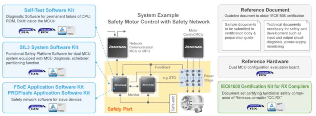
Figure 6. Renesas Solution overview, how it supports on system example
The highly competitive Renesas Functional Safety Package ensures that the developers will only need to focus on system development as MCU based SW package and certification paperwork is readily available to integrate. Our TÜV Rheinland Certified Self-test and SIL3 System SW kit provides all the diagnosis and safety task required for MCUs. Finally, the reference document, the documentation guide, for Functional Safety system development under IEC61508 provides additional assistance on attaining system certification.
In conclusion, utilizing the Renesas functional safety solutions package provides one with more time to complete one’s system development time which in turn can achieve a reduction in the overall cost and time to market. Please visit our website IEC61508 Functional Safety Solution for more details and contact your local Renesas sales representative to discuss your next functional safety solution needs.
Previous blog post: Meet the Risk Buster: Functional Safety in Industries


