Radar Transceivers: Key Components for ADAS & Autonomous Driving
- Blog 1: Why Do We Need Radar?
- Blog 2: Basics of FMCW Radar
- Blog 3: Radar Range: How Far Can a Radar "See"?
- Blog 4: Radar Resolution: How Accurate Can a Radar Be?
- Blog 5: Radar Architecture: How to Connect Different Radar Sensors
- Blog 6: How to connect the antennas?
- Blog 7: Antennas for Automotive Radar
In the last entry of this blog dedicated to automotive radar, we analyzed the parameters of the MMIC radar transceiver, which impacted the range of detection. Here, we will explain how we can increase the accuracy of the detection, focusing on the field of view, and the range and angular resolution. Indeed, it is not enough to “look” as far as possible. It is also important to be able to distinguish between two targets close to each other, either in range or in angle (bearing).

Range Resolution
The range resolution of the radar defines is the ability to distinguish between different targets placed in the same angular direction (bearing) but at different distances from the radar. The signals reflected by two targets are shifted in the temporal domain.
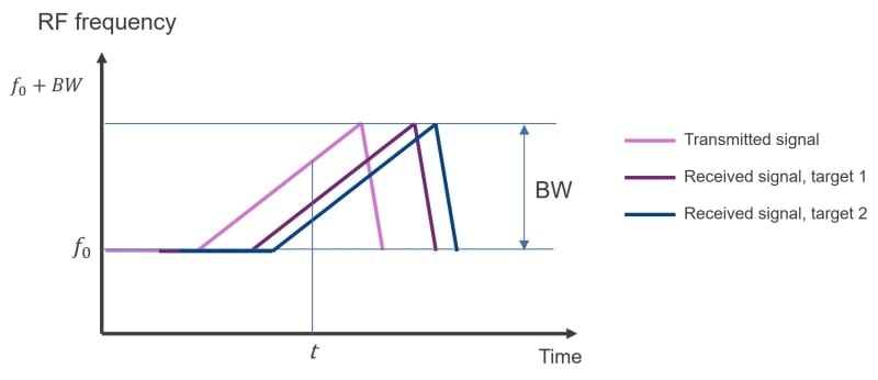
After performing an FFT (Fast Fourier Transformation) two separate baseband frequencies (frequency shift) corresponding to each target are obtained.
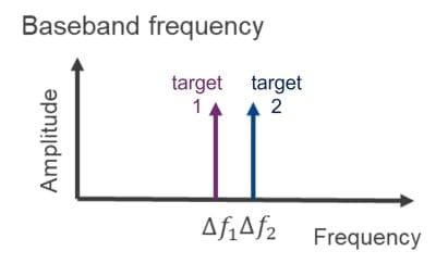
The closer the two targets, the smaller the difference between the baseband frequencies ∆f1 and ∆f2. At a certain point, the radar system will not be able to separate them anymore. This minimum frequency shift/distance corresponds to one FFT bin. The minimum frequency difference ∆f that can be resolved for an observation time Tc is:
∆f can be improved (i.e. minimized) by increasing the observation time.
The distance between targets ∆R is directly related to ∆f:
With c being the light velocity.
Where S is the slope of the transmitted radar signal (chirp rate in Hz/s). As the bandwidth is the product of the slope of the signal and its duration, the range resolution dres can be written as a function of the signal bandwidth:
The bandwidth of the radar chip will therefore have a direct influence on the achievable range resolution:
Table 1. Range resolution vs. radar signal bandwidth
| Bandwidth | Range resolution dres |
|---|---|
| 250MHz | 60cm |
| 500MHz | 30cm |
| 1GHz | 15cm |
| 2GHz | 7.5cm |
| 4GHz | 3.75cm |
A large bandwidth will be needed for applications that require high resolution, for example for imaging radar. Yet, other applications like long-range radar do not need and accuracy in the order of magnitude of centimeters, so a smaller bandwidth would be enough. This is important to consider, as the maximum radar range is inversely proportional to the bandwidth:
For a given sampling rate Fs, increasing the bandwidth will reduce the range of detection.
Field of View
It is also important to determine the direction of the target (bearing) in an unambiguous way. This is only possible within the field of view (FOV) of the radar, which defines the angular coverage of the radar in azimuth (horizontal plane) and elevation (vertical plane).
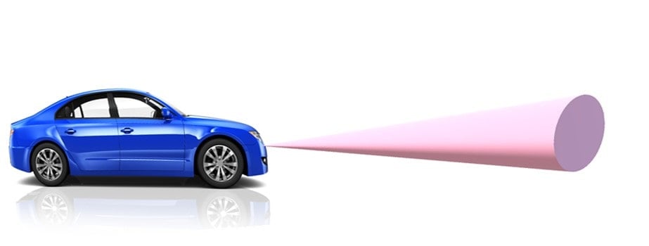
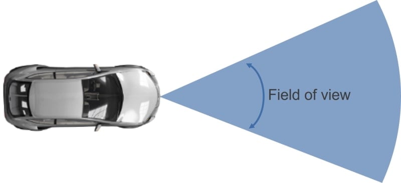
Automotive radars use multiple receiving antennas, to determine the angle of arrival (AoA) of the reflected signal, and thus the angular position of the obstacles. Therefore, the geometry of the antenna array will be a limiting factor for the field of view.
If a single transmitting antenna is considered, the FOV will be determined by the geometry and radiation properties of the receiving antennas. Let us consider the case of two receiving antennas separated by a distance d.
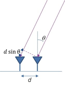
The angle of arrival of the signal can be calculated by comparing the phase shift of the signal received by each of the antennas. The phase shift in the received signal depends on the frequency (wavelength) and the distance between the antennas, as shown in Figure 6:
The angular range for unambiguous measurement of the angle of arrival is the range in which the phase difference varies monotonously from -180° to +180°, so the theoretical FOV, from a purely geometric point of view, is given by:
The maximum field of view is achieved when all angles of arrival from -90° to +90° can be detected. This is the case when the distance between the antennas equals half of a wavelength at the frequency of operation, that is:  .
.
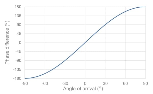
In the case of automotive radar at 77GHz, the theoretical FOV can be maximized using a separation between the antennas of approximately 2mm. This is assuming the antennas used are isotropic radiators. In real life, the field of view will be further limited by the radiation patterns of the antennas.
Let us consider now that the receiving antennas are two uniform linear arrays of patches as shown in Figure 8.
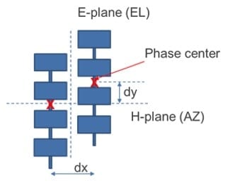
In this case, the antenna pattern in azimuth is very wide (corresponding to a patch antenna), so its influence on the FOV is limited. The main limiting effect will be the separation dx between the rows, and the FOV can be calculated using eq. (6).
For the elevation FOV, all the patches in a vertical row are considered as a single antenna. To calculate the theoretical FOV we need to consider the phase center of the row (that is, the imaginary point where the total radiation of the row is originated). The theoretical FOV in elevation will be limited by the vertical separation between the phase centers of each vertical row (dy). If this separation is half a wavelength, we could in principle get the maximum FOV. Yet, in this case, the half power beamwidth (HPBW) of the antenna is much smaller (~20° - 25°), so the detection would not be possible outside the antenna beam. In this case, the radiation pattern will be the limiting factor of the FOV.
Angular Resolution
As in the case of the range resolution, it is also important to be able to distinguish between two separate targets placed at different angles (bearings), but at the same range. Here, the frequency shift due to the signal delay cannot be used to identify the signals from each of the targets. Again, special diversity is needed, with multiple antennas at different locations.
The angular resolution θres indicates then the minimum angular separation that can be resolved by the radar. For a single transmit antenna it can be calculated as:
N being the number of receive antennas and θ the angle of arrival. The angular resolution is at is maximum for bearings close to the boresight direction (θ = 0°):
If we consider that the antennas are separated  , to maximize the FOV, the angular resolution will be independent of the frequency and be only determined by the number of receive antennas.
The resolution can therefore be increased by increasing the number of antennas. This is only possible by adding more channels to the radar MMIC transceiver. The resolution can be further improved by using multiple transmit antennas for MIMO (Multiple Input, Multiple Output) and super-resolution post processing.
Conclusion
In this entry, the parameters that determine the accuracy of a radar system have been presented. The range resolution is directly linked to the performance of the radar transceiver, while the angular resolution and field of view will also depend on the geometry of the antennas used in the radar system.
In the next entry of the blog, we will focus on different radar architectures that are needed for current and future applications.
