A photocoupler normally operates by sending light radiated by the input of a DC current to the LED to the photodiode on the receiving side. However, when an AC (alternating current) is input to the LED, the photocoupler not only outputs every half cycle, but the LED is also in danger of receiving fatal damage.
An AC input capable photocoupler, on the other hand, enables the input of an AC current. Moreover, because output corresponds to full cycles, it is easy to make the output of it continuous and quiet.
The internal connection of an AC input capable photocoupler and its operating principle are shown below.
1. Internal Connection
Figure 1 shows the internal pin connections in an AC input capable photocoupler (left) and a normal photocoupler (right).

Figure 1. Differences in Internal Connection
Because a normal photocoupler has one LED on the input side, as shown in the figure on the right in Figure 1, the LED lights and a signal is transferred only when current is applied in the direction of pin 1 to pin 2 (DC input type).
However, for the AC input capable type shown in the figure on the left in Figure 1, because there are two LEDs connected back-to-back on the input side, LED1 lights and a signal is transferred when current is applied in the direction of pin 1 to pin 2, and LED2 lights and a signal is transferred when current is applied in the reverse direction of pin 2 to pin 1.
In other words, in an AC input capable photocoupler, a signal can be transferred even if the polarity between pins 1 and 2 is switched from positive to negative and vice versa.
Hence the name "AC input capable photocoupler".
2. Operating principle
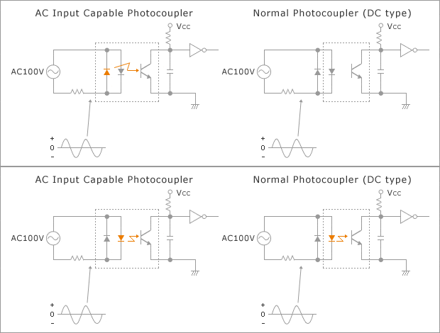
The figure on the left in Figure 2 shows a basic circuit connection example when AC 100 V is input to an AC input capable photocoupler via a current-limiting resistor.

Figure 2. Basic Circuit Connection
Unlike the normal photocoupler on the right, an external back-to-back diode is not required for the AC input capable photocoupler because it incorporates two LEDs.
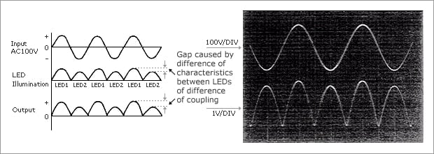
Figure 3 shows the relationship between the input and output signals of the AC input capable photocoupler.

Figure 3. Input and Output Operation Waveforms
The output signal is generally used after smoothing by a capacitor, etc., as shown in Figure 2.
However, by using an AC input capable photocoupler, an output signal can be obtained in the form of a full-wave rectified AC input signal, enabling the capacitor to be used at close to half the capacitance of when a normal photocoupler is used.
This makes the AC input capable photocoupler effective for circuit simplification and package miniaturization.