Radar Transceivers: Key Components for ADAS & Autonomous Driving
- Blog 1: Why Do We Need Radar?
- Blog 2: Basics of FMCW Radar
- Blog 3: Radar Range: How Far Can a Radar "See"?
- Blog 4: Radar Resolution: How Accurate Can a Radar Be?
- Blog 5: Radar Architecture: How to Connect Different Radar Sensors
- Blog 6: How to connect the antennas?
- Blog 7: Antennas for Automotive Radar
What is Radar?
Radar (Radio Detection and Ranging) uses radio waves to detect objects in the environment. It allows determining the distance (known as range), angular position (bearing) and velocity. Radar technology was developed for military use during World War II, but has now many civil applications, including air or marine traffic control, astronomy, ocean and meteorological monitoring, altimetry, geological observations, and automotive applications.
The radar system includes a transmitter, which emits an electromagnetic radio frequency wave (radar signal) in a certain direction. The signal reflected off the target objects (echo) is then detected by the radar receiver. The magnitude of the reflection is determined by the object’s material properties, size and shape (radar cross section RCS). By processing this reflected signal, the properties of the target can be determined.
FMCW Radar
Automotive radar systems operate using a so-called Frequency Modulated Continuous Wave (FMCW). The system transmits a continuous wave at a certain frequency, which is then modulated over a period of time T. This gives the transmitted signal a “time stamp". The signal travels then to the target and part of it is reflected back. The radar will detect the reflected signal and compare it to the original one by mixing them and processing the resulting signal. A simplified schematic is presented in Figure 1.

Figure 1. FMCW automotive radar – Principle and building blocks
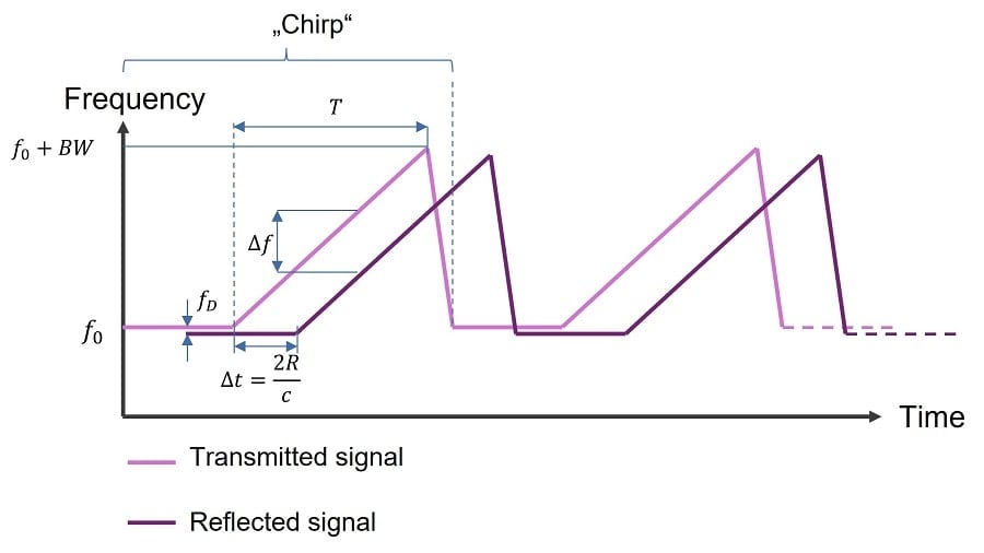
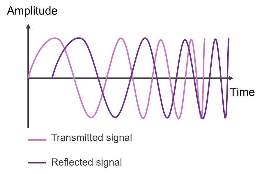
An example of this radar signal is shown in Figures 2 and 3. The returned signal is similar in shape to the transmitted one, but shifted in time as the two-way trip from the radar to the target takes an amount of time ∆t that is proportional to the distance to the target R:
With c being the light velocity.

Figure 2. Sawtooth FMCW radar signal: frequency vs. time

Figure 3. FMCW radar signal: amplitude vs. time
By comparing the reflected wave with the original signal at any given moment of time, a frequency shift ∆f can be observed. This shift allows determining the range R for each period of the signal or “chirp”. If the signal is monitored over several chirps, an additional frequency shift fD will be detected for a target moving towards or away from the radar, due to the Doppler effect. This allows for determining the velocity of the target. Finally, if different channels are considered, using spatially distributed antennas, the direction of arrival of the signal can be established, to obtain the 2D or 3D position of the target.
That means that to have 4D detection (range, azimuth and elevation direction, and velocity), a space-time processing of the signal is needed. For that, the signal needs to be digitized and saved for further processing. The first step will be creating the so-called “radar cube”.
Radar Processing - The Radar Cube
The radar data cube is a three-dimensional graphic depiction of the space-time processing of the stored radar data. It summarizes the three basic steps required to obtain range, velocity and bearing information.
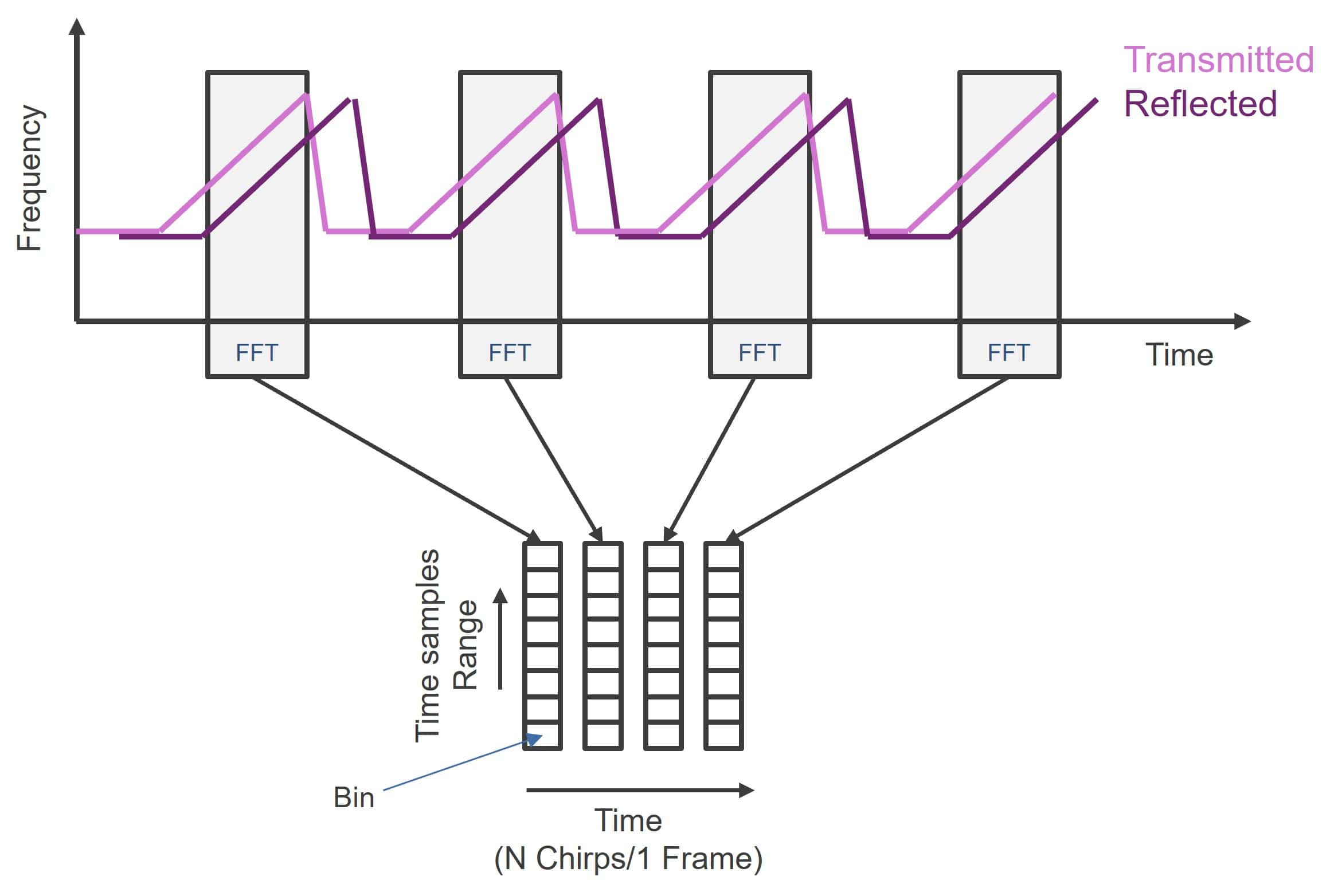
As mentioned above, the received signal is sampled for processing. The first step is performing an FFT (Fast Fourier Transformation) so that each sample corresponds to a “bin” to obtain the range information over the so-called “fast time”. This is illustrated in Figure 4. The procedure is repeated for each of the chirps that form a frame.

Figure 4. Radar processing: range FFT
Once all the chips in a frame have been acquired, saved, and processed, the Doppler-FFT is performed to obtain information about the velocity of the target. This evaluation is done once per frame, i.e., every N chirps. Therefore, it is also known as “slow time”. Finally, the data from the spatial along all the available channels are combined, to get the third dimension of the radar cube, which contains the information on the spatial position of the target. The graphic representation of the radar cube is shown in Figure 5.

Figure 5. The radar cube
Automotive Radar Modules
The deployment of automotive radar has been facilitated by advances in semiconductor technology, especially silicon-based. While in the early 2010s multi-channel radar transceivers were integrated on a single GaAs (Gallium arsenide) MMIC (Monolithic Microwave Integrated Circuits), nowadays the use of Silicon Germanium (SiGe) has increased the integration density and lowered the costs for mass production. The next challenge will be the transition to CMOS (Complementary Metal Oxide Semiconductor), which will allow the integration of further digital circuits on the die while keeping good RF performance.
Yet, to implement a radar system, each radar module must include one or more MMIC transceivers, which emit the radar signal, detect the echoes from the obstacles and perform some signal conditioning and digitation to prepare the raw radar data for further analysis by a processing unit. The latter can be a microcontroller unit (MCU) for basic processing, but with the advances in radar technology, SoCs (System-on-Chips) are increasingly used to implement more sophisticated analysis, detection and tracking of the targets.
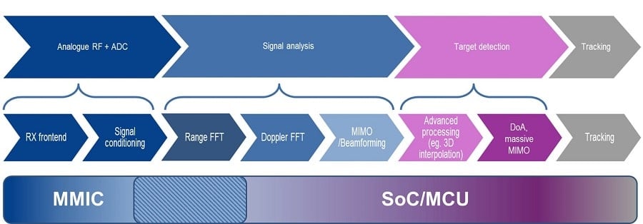
Figure 6 illustrates the different steps in the processing of the radar signals over the whole receiving path. While analog RF processing and the conversion to digital signals are always performed on the MMIC, the interfaces for the signal analysis are not fixed. With increasingly complex radar architectures and signal processing, some steps such as the first FFT can already be performed on the MMIC. Moreover, it is also possible to combine the radar transceiver and the processing unit in a single, monolithic chip for some applications like corner radars.

Figure 6. Radar processing steps
In the future, more complex architectures could be implemented, with several satellite radars distributed around the car. The radar modules would then perform only a limited amount of pre-processing before delivering the data, e.g., range and point cloud, to a central control unit (ECU), which could then apply more advanced processing and data fusion, not only of the satellite radar modules but also of other sensors.
Conclusion
This entry has provided an overview of the operating principle of the FMCW radar, used in automotive applications, and its implementation using MMICs and MCU/SoC. In the next blog entry, we will look into how the MMIC performance affects the detection range.
