In recent years, the power consumption of information systems has been increasing as more intelligent and IoT connectivity functions are implemented on many battery-powered applications such as home appliances, industries, and consumer equipment. Considering the further growth of the information society in the future, it is essential to reduce the power consumption of individual terminals that consist of information systems.
Renesas RA MCU supports a variety of low-power functions such as low-power modes (sleep mode, standby mode and snooze mode), power control modes, and independent clock-supply-stop functions for built-in peripheral functions to meet various customer needs for low power applications. Especially, Snooze mode, which allows a peripheral function to autonomously operate without CPU intervention is very unique and can significantly reduce the power consumption of applications that run in an intermittent operation.
Example of the peripheral functions that can be run autonomously and mutually in Snooze mode on the RA2E1 MCU:
- Timers (AGT, RTC): Generates an interrupt regularly
- 12-bit A/D converters (ADCs): Converts analog signals from sensors to 12-bit digital values
- Data transfer controller (DTC): Transfers data (e.g., data transfer from a peripheral register to RAM or the other peripheral register).
- Data operation circuit (DOC): Circuit capable of performing comparison, addition and subtraction of 16-bit data.
The combinational operation of peripheral modules in Snooze mode is realized by the event link controller (ELC) equipped with the MCU. By linking the above module events with the ELC, the combinational operation below can be performed automatically without software processing: starts ADC conversion - transfers the AD conversion result to RAM - do data comparison and judge whether or not to wake up CPU or go back to standby.
The article below introduces the Low Power Data Logger Application (R30AN0392) utilizing Snooze mode.
Low Power Data Logger Application Notes Overview
This application note explains how to use the RA2E1 MCU and Flexible Software Package (FSP) for data logger applications that require low-power consumption for long battery life. The sample application example keeps the CPU in standby continuously but acquires analog sensor data, transfers the AD conversation result to a RAM buffer, and makes a threshold determination for the data at low power consumption.
The behavior of Low Power Data Logger Application:
- MCU enters Software Standby mode
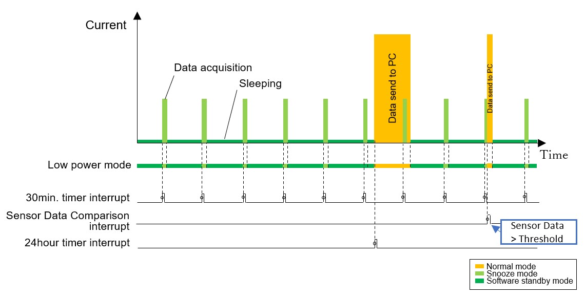
- Transition to Snooze mode by AGT interrupt every 30 minutes
- Executes A/D conversion, RAM transfer, and threshold comparison by ELC-linked operation.
- If the result of the data comparison is less than the threshold value, the process returns to step 1.
- If the result of the data comparison is greater than or equal to the threshold value, the process proceeds to step 4.
- Transition from Snooze mode to Normal mode (CPU operation mode)
- The sensor data stored in the RAM is outputted by UART communication using the serial communication interface (SCI), and the process returns to 1.
The low-power mode is also canceled by the 24-hour interrupt generated by the real-time clock (RTC), and the sensor data stored in the RAM is output by UART communication.
A series of processing flows and power image:

Developing Low-Power Applications Using Flexible Software Package (FSPs)
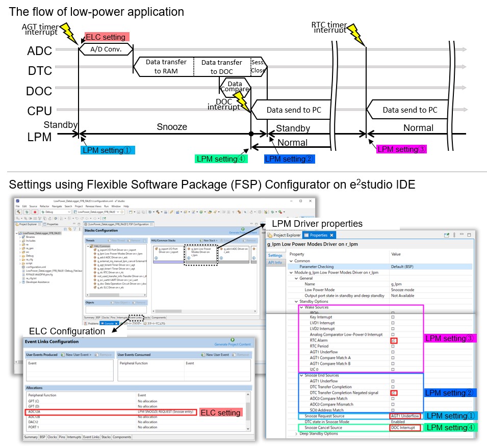
The FSP for the Renesas RA family provides the various HAL drivers required to develop low-power applications, and the integrated development environment e² studio supports intuitive configurators and intelligent code generation to easily and quickly develop low-power applications, including event linking with ELC.
The low-power data logger application in this article can easily be implemented with support from the FSP configurator.
- Set the low-power mode transition conditions using LPM HAL driver properties.
- Set the A/D converter start trigger by ELC in the Event Links tab page.
- Press "Generate Project Content" to automatically generate setup files to the project folder.
- User application code implementation. By using the Developer Assistant function, you can add driver API calls to the source code by dragging and dropping them.

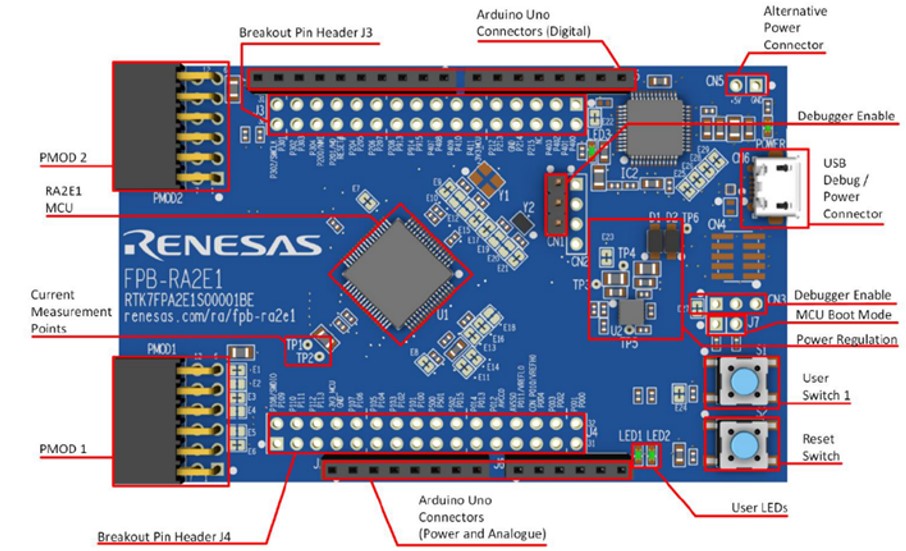
FPB-RA2E1 kit
RA2E1 MCU Group Evaluation Kit FPB-RA2E1 implements a variety of connectors that allow access to all the pins on the RA2E1 MCU, onboard E2 emulator, user switches, and LEDs to get started with the RA2E1 MCU and develop embedded ecosystem applications using FSP and e² studio quickly. FPB-RA2E1 also provides some test points to evaluate the MCU performance such as current consumption.

As described in this article, the various low-power features and peripheral functions on the RA2E1 MCU can be quickly evaluated using the FSP-e² studio configurator and the FPB-RA2E1 kit.
Download the application note (R30AN0392) and purchase the FPB-RA2E1 kit to accelerate your designs using the low-power RA2E1 MCU today!
