Overview
The field of motor control has undergone rapid expansion due mainly to the advantages of semiconductors in both power and signal electronics and the processing capability of micro-electronic microprocessors and DSPs. These technological improvements have enabled the development of effective drive control with ever lower power dissipation hardware and ever more accurate control structures. The electrical drive controls have become more accurate in the sense that not only are the DC current and voltage controlled but also the three-phase currents and voltages are managed by the combined use of MCU and software algorithms.

Comparison of Different Motor Control Algorithms
The table below captures the salient characteristics of the most prevalent motor control algorithms.
| Control Algorithm | Motor Type | Torque Controllability | Feedback Sensors | MCU Processing Requirements |
|---|---|---|---|---|
| TRIAC Control | Universal / DC | No Torque Control | Not Required | Not Required |
| PWM Chopper Control | Universal / DC | No Torque Control | Not Required | 8 bit |
| V/F Control | AC | Poor Dynamic Torque Control | Not Required | 8-16 bit |
| Trapezoidal Drive Control | BLDC | High-Harmonic Loss, High-Torque Ripple | Hall Sensor | 8-16 bit |
| Sinusoidal Drive Control | BLDC, AC | Low-Harmonic Loss, Low-Torque Ripple | Hall Sensor, Encoder | 16-32 bit |
| Simplified Vector Control | BLDC, AC | Low-Harmonic Loss, Low-Torque Ripple | Hall Sensor, Encoder | 16-32 bit |
| Vector Control | BLDC, AC | Low-Harmonic Loss, Low-Torque Ripple | Hall Sensor, Encoder | 32 bit |
| Sensorless Trapezoidal Drive Control | BLDC | High-Harmonic Loss, High-Torque Ripple | Not Required (Back-EMF) | 16 bit |
| Sensorless Vector Control | BLDC, AC | Low-Harmonic Loss, Low-Torque Ripple | Not Required | 32 bit |
Universal DC Motor Control Algorithms
Speed control of Universal Motors typically employs two schemes:
- Phase angle Control
- PWM Chopper control
Phase Angle Control
It is the simplest method to control the speed of a universal motor. Speed control is achieved by the varying the firing angle for the TRIAC. Phase angle control is very cost-effective solution but not very efficient and prone to EMI.

The figure above shows the Phase Angle Control mechanism typically employed for speed control of the TRIAC. A phase shift of the TRIAC gate's pulses allows the effective voltage, seen by the motor to be varied and hence the speed of the motor. A Zero Crossing Detection circuit is used to establish a timing reference for delaying the firing of the gate pulses.
PWM Chopper Control
PWM control is a more advanced solution for controlling the speed of a universal motor. In this method rectified AC line voltage is switched at a high frequency by a Power MOSFET or IGBT device to generate time-varying voltage for the motor.

The switching frequency is usually in the range of 10 to 20 KHz to eliminate acoustic noise. This method of universal motor control can achieve better current control, better EMI behavior, and hence more efficiency.
BLDC Motor Control Algorithms
Brushless motors are not self-commutating, and hence are more complicated to control.
BLDC motor control requires knowledge of the rotor position and mechanism to commutate the motor. For closed-loop speed control, there are two additional requirements, measurement of the motor speed and/or motor current and PWM signal to control the motor speed and power.
BLDC motors can use edge-aligned or center-aligned PWM signals depending on the application requirements. Most applications, that only require variable speed operation, will use six independent edge-aligned PWM signals. This provides the highest resolution. If the application requires servo-positioning, dynamic braking, or dynamic reversal, it is recommended that complementary center-aligned PWM signals be used.
To sense the rotor position BLDC motors use Hall Effect sensors to provide absolute position sensing. This results in more wires and higher costs. Sensorless BLDC control eliminates the need for Hall effect sensors, using the back-EMF (electromotive force) of the motor instead to estimate the rotor position. Sensorless control is essential for low-cost variable speed applications such as fans and pumps. Refrigerator and air conditioning compressors also require sensorless control when using BLDC motors.
Dead Time Insertion and Compensation
Many different control algorithms have been used to provide control of BLDC motors. Typically, the motor voltage is controlled using a power transistor operating as a linear voltage regulator. This is not practical when driving higher-power motors. High-power motors must use PWM control and require a microcontroller to provide starting and control functions.
The control algorithm must provide three things:
- PWM voltage to control the motor speed
- Mechanism to commutate the motor
- Method to estimate the rotor position using the back-EMF or Hall Sensors
Pulse-width modulation is used to apply a variable voltage to the motor windings. The effective voltage is proportional to the PWM duty cycle. When properly commutated, the torque-speed characteristics of the BLDC motor are identical to a dc motor. The variable voltage can be used to control the speed of the motor and the available torque.
The commutation of the power transistors energizes the appropriate windings in the stator to provide optimum torque generation depending on the rotor position. In a BLDC motor, the MCU must know the position of the rotor and commutate at the appropriate time.
Trapezoidal Commutation of BLDC Motor
One of the simplest methods of control for DC brushless motors uses what is termed Trapezoidal commutation.

In this scheme, the current is controlled through motor terminals one pair at a time, with the third motor terminal always electrically disconnected from the source of power.
Three Hall devices embedded in the motor are usually used to provide digital signals that measure rotor position within 60-degree sectors and provide this information to the motor controller. Because at any time, the currents in two of the windings are equal in magnitude and the third is zero, this method can only produce current space vectors having one of six different directions. As the motor turns, the current to the motor terminals is electrically switched (commutated) every 60 degrees of rotation so that the current space vector is always within the nearest 30 degrees of the quadrature direction.

The current waveform for each winding is therefore a staircase from zero, to positive current, to zero, and then to negative current.
This produces a current space vector that approximates smooth rotation as it steps among six distinct directions as the rotor turns.
In motor applications such as air conditioners and refrigerators use of Hall-Effect sensors is not a viable option. Back-EMF sensors that sense the back EMF in the unconnected winding can be used to achieve the same results
The trapezoidal-current drive systems are popular because of the simplicity of their control circuits but suffer from a torque ripple problem during commutation.
Sinusoidal Commutation for BLDC Motors
Trapezoidal commutation is inadequate to provide smooth and precise motor control of brushless DC motors, particularly at low speeds. Sinusoidal commutation solves this problem. This is because the torque produced in a three-phase brushless motor (with a sine wave back-EMF) is defined by the following equation:
Shaft Torque = Kt [ IR Sin(φ) + IS Sin(φ+120) + IT Sin(φ+240)]; where:
- φ is the electrical angle of the shaft,
- Kt is the torque constant of the motor and
- IR , IS and IT are the phase currents.
If the phase currents are sinusoidal: IR = I0 Sin(φ); IS = I0 Sin (φ+120); IT = I0 Sin (φ+240); this reduces to:
- Shaft Torque = 1.5I 0 * Kt (a constant independent of the shaft angle)
Sinusoidally commutated brushless motor controllers attempt to drive the three motor windings with three currents that vary smoothly and sinusoidally as the motor turns. The relative phases of these currents are chosen so that they should result in a smoothly rotating current space vector that is always in the quadrature direction with respect to the rotor and has constant magnitude. This eliminates the torque ripple and commutation spikes associated with trapezoidal commutation.
In order to generate smooth sinusoidal modulation of the motor currents as the motor turns, an accurate measurement of rotor position is required. The Hall devices provide only a coarse measure of rotor position and are inadequate for this purpose. For this reason, angle feedback from an encoder, or similar device, is required.
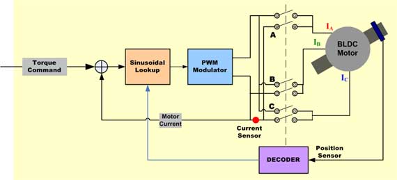
Since the winding currents must combine to produce a smoothly rotating current space vector of constant magnitude, and because the stator windings are oriented 120 degrees apart from each other, currents in each winding must be sinusoidal and phase-shifted by 120 degrees. Position information from the encoder is used to synthesize two sinusoids, one 120-degree phase shifted from the other. These signals are then multiplied by the torque command so that the amplitudes of the sine waves are proportional to desired torque. The result is two sinusoidal current command signals appropriately phased to produce a rotating stator current space vector in the quadrature direction.
The sinusoidal current command signals are provided as inputs to a pair of P-I controllers that regulate current in the two appropriate motor windings. The current in the third motor winding is the negative sum of the currents in the controlled windings and therefore cannot be separately controlled. The output from each P-I controller is fed to a PWM modulator and then to the output bridge and two motor terminals. Voltage applied to the third motor terminal is derived as the negative sum of the signals applied to the first two windings, as appropriate for three sinusoidal voltages each separated by 120 degrees.
To the extent that the actual output current waveform accurately tracks the sinusoidal current command signals, the resulting current space vector is smoothly rotating, constant in magnitude and oriented in the quadrate direction as desired.
Sinusoidal commutation results in the smoothness of control that is generally unachievable with trapezoidal commutation. However, while it is very effective at low motor speeds, it tends to fall apart at high motor speeds. This is because as speed goes up the current loop controllers must track a sinusoidal signal of increasing frequency. At the same time, they must overcome the motor back-EMF that also increases in amplitude and frequency as speed goes up.
Because the P-I controllers have limited gain and frequency response, the time-variant perturbations to the current control loop cause phase lag and gain error in the motor currents. Higher speeds result in larger errors. This perturbs the direction of the current space vector relative to the rotor, causing it to shift away from the quadrature direction.
When this happens, less torque is produced by a given amount of current and therefore more current is required to maintain torque. Efficiency deteriorates.
This degradation continues as speed increases. At some point, motor current phase shift crosses through 90 degrees. When this happens torque is reduced to zero. With sinusoidal commutation, speeds above this point result in negative torque and are therefore impossible.
AC Motor Control Algorithms
Scalar Control
Scalar control (or V/Hz control) is a simple technique to control speed of induction motor.
The steady-state model of induction motor is mainly used to derive the technique, so transient performance is not possible. The system has no current loop. To control the motor the three-phase supply is varied only in magnitude and frequency.
Vector Control or Field Orientation Control
Torque in an electric motor varies as a function of the stator and rotor fields and is at its peak when the two fields are orthogonal to each other. In scalar-based control the angle between the two fields varies considerably.
Vector control seeks to recreate the orthogonal relationship in the AC motor. To control the torque producing current separately from the magnetic flux producing current so as to achieve the responsiveness of a DC machine.
Vector control of an AC induction motor is analogous to the control of a separately excited DC motor. In a DC motor, the field flux ΦF produced by the field current IF is perpendicular to the armature flux ΦA produced by the armature current IA. These fields are decoupled and stationary with respect to each other. Therefore when the armature current is controlled to control torque the field flux remains unaffected enabling a fast transient response.
Field Oriented Control (FOC) of a 3-phase AC motor involves imitating the DC motors' operation. All controlled variables are transformed to DC instead of AC via mathematical transformation. The goal is to control torque and flux independently.
There are two methods for Field Oriented Control (FOC):
- Direct FOC: Rotor flux angle is directly computed from flux estimation or measurement.
- Indirect FOC: Rotor flux angle is indirectly computed from available speed and slip computation.
Vector Control requires knowledge of the rotor flux position and can be computed using advanced algorithms from knowledge of the terminal current and voltages using a dynamic model of the AC induction motor. However, from an implementation standpoint, the need for computational resources is critical.
Different methods can be used to implement the vector control algorithm. Feed forward techniques, model estimators and adaptive control techniques can all be employed to enhance response and stability.
Vector Control of AC Motors: An in-depth look
At the core of vector control algorithm are two important mathematical transforms: Clarke Transform, Park Transforms and their inverse. Use of the Clarke and Park transforms brings the stator currents which can be controlled into the rotor domain. Doing this allows a motor control system to determine the voltages that should be supplied to the stator to maximize the torque under dynamically changing loads.
Clarke Transformation: The Clarke mathematical transform modifies a three-phase system to a two-coordinate system.

where Iα and Iβ are components of the orthogonal reference plane and Io is the homoplanar component which is of little significance

Park Transformation: The Park mathematical transform converts two-phase stationary system vectors to rotating system vectors

The two phases α, β frame representation calculated with the Clarke transform is then fed to a vector rotation block where it is rotated over an angle θ to follow the d, q frame attached to the rotor flux. The rotation over an angle θ is done according to the above formulas.
Basic Scheme for Field Oriented Vector Control of AC Motor:
Figure 2 shows the basic scheme for a Field Oriented Vector Control for an AC Motor.
The Clarke transform uses three-phase currents IA, IB and IC to calculate currents in the two-phase orthogonal stator axis: Iα and ;Iβ. These two currents in the fixed coordinate stator phase are transformed to the Isd and Isq currents components in the d, q frame with the Park transform. The currents Isd, Isq and the instantaneous flux angle θ, calculated by the motor flux model, are used to calculate the electric torque of an AC induction motor.

These derived values are compared against the reference and updated by a PI controller.
Comparison between Scalar and Vector Control for Motors
| Control Parameters | V/Hz Control | Vector Control | Sensorless Vector Control |
|---|---|---|---|
| Speed Regulation | 1% | 0.001% | 0.05% |
| Torque Regulation | Poor | +/- 2% | +/- 5% |
| Motor Model | Not Required | Required | Requires Accurate Model |
| MCU Processing Power | Low | High | High + DSP |
An inherent advantage of Vector-based motor control is that the same scheme can be used to control various types of AC, PM-AC or BLDC motors by selecting the appropriate mathematical models for the respective motors.
Vector Control of BLDC Motors
BLDC motors are also prime candidates for Field Oriented Vector control. Brushless motors that adopt an FOC approach can achieve even higher efficiencies, up to 95 percent and are efficient at the very highest speed range of the motor.
Stepper Motor Control Algorithms
Stepper motor control typically employs bidirectional drive current and the motor is stepped by switching the windings in sequence. For a motor of this type, there are three possible drive sequences.

- One Phase On Full Step Drive: In this control mode, the windings are energized in the following sequence AB/CD/BA/DC (BA means that the winding AB is energized but in the opposite sense). This sequence is known as "one phase on" full step or wave drive mode. Only one phase is energized at any given moment.
- Two Phase On Full Step Drive: In this mode, two phases are energized together so that the rotor always aligns itself between two pole positions. Called "two-phase-on" full step, this mode is the normal drive sequence for a bipolar motor and yields the highest torque.
- Half-Step Mode: This method combines One Phase On and Two Phase On modes to energize one phase, then two, then one, etc., so that the motor moves in half-step increments. This sequence, known as half-step mode, halves the effective step angle by which the motor moves for each excitation but yields a lower torque.
For rotation in the opposite direction (counter-clockwise), any of the above three modes can be used except that the order is reserved.
Stepper motors usually have multiple poles to reduce the step angle to a few degrees but the number of windings and the drive sequences are unchanged.