Overview
Description
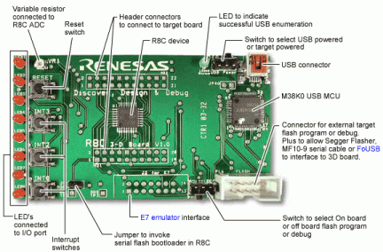
The 3-D board consists of an R8C/11 microcontroller (MCU) mounted on to a circuit board with 8 independent LEDs connected to an I/O port to allow simple visual output from the MCU. Three switches allow interrupt input to the MCU and a variable resistor is connected to an analog-to-digital converter (ADC) input allowing an analog voltage to be measured. The board can be interfaced to a PC via the USB socket where C-coded programs may be downloaded to the MCU using the KD30 debugger software provided. Also provided is a header connector around the MCU which provides access to the MCU I/O pins.
Hardware Overview
The 3-D board includes:
- R8C/11 Flash microcontroller.
- Main oscillator (the frequency depends on the MCU variant).
- 8 independent LEDs (2mA low current type) connected to an I/O port.
- 4 push switches connected to the Interrupt and RESET pins of the MCU.
- Variable resistor connected to the A-D converter input AN0.
- MCU header connector (0.1" pitch, double-row) to allow connection to all the MCU port pins.
- USB Mini-B socket connected to a Renesas 38K0 USB microcontroller acting as a USB-to-UART interface. The green Status LED lights when the USB microcontroller has completed the set-up negotiation with the USB host.
- Power is supplied by the USB hub/host or a DC power supply connected to the header connector. USB power is selected by moving the "USB Power" switch to "On".
- The Flash connector, PL6, can be used to program an external target M16C/R8C.
- 3DKR8C/11U 3-D Board Schematic (PDF)
Note
This product is available only in Europe.
Features
- Demo tool where the basic functions of the MCU can be tested or demonstrated. Sample programs on the CD-ROM can be downloaded to the MCU via the USB port.
- Benchmarking target board for evaluating the MCU performance, allowing compilation, debugging and benchmarking of the user's own code.
- Simple in-circuit emulator. If fitted with the header connectors (0.1"; pitch, double-row headers) it can function as a simple in-circuit emulator, where hardware or software can be debugged. The user's target hardware is built to allow this with the compatible PCB sockets.
- Flash programming tool. Using the external Flash connector the 3-D board is able to program an external R8C device.
- Kit Contents
- 3-D board
- USB cable
- Jumper link
- Header Connectors
- Kickstarter CD-ROM including trial IAR and Tasking compilers, source level debuggers and extensive tutorial code examples.
