Overview
Description
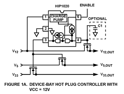
The HIP1020 applies a linear voltage ramp to the gates of any combination of 3. 3V, 5V, and 12V MOSFETs. The internal charge pump doubles a 12V bias or triples a 5V bias to deliver the high-side drive capability required when using more cost-effective N-Channel MOSFETs. The 5V/ms ramp rate is controlled internally and is the proper value to turn on most devices within the Device-Bay-specified di/dt limit. If a slower rate is required, the internally-determined ramp rate can be over ridden using an optional external capacitor. When VCC = 12V, the charge pump ramps the voltage on HGATE from zero to 22V in about 4ms. This allows either a standard or a logic-level MOSFET to become fully enhanced when used as a high-side switch for 12V power control. The voltage on LGATE ramps from zero to 16V allowing the simultaneous control of 3. 3V and/or 5V MOSFETs. When VCC = 5V, the charge pump enters voltage-tripler mode. The voltage on HGATE ramps from zero to 12. 5V in about 3ms while LGATE ramps to 12. 0V. This mode is ideal for control of high-side MOSFET switches used in 3. 3V and 5V power switching when 12V bias is not available.
Features
- Rise Time Controlled to Device-Bay Specifications
- No Additional Components Required
- Internal Charge Pump Drives N-Channel MOSFETs
- Drives any Combination of One, Two or Three Outputs
- Internally-Controlled Turn-On Ramp
- Optional Capacitor Selects Slower Rates
- Prevents False Turn on During Hot Insertion
- Operates using 12V or 5V Bias
- Improves Device Bay Peripheral Size Cost and Complexity
- Minimal Component Count
- Tiny 5-Pin SOT23 Package
- Controls Standard and Logic-Level MOSFETs
- Compatible with TTL and 3.3V Logic Devices
- Shutdown Current <1µA
- Operating Current <3mA
Comparison
Applications
- Device Bay Peripherals
- Hot Plug Control
- Power Distribution Control
Documentation
|
|
|
|
|---|---|---|
| Type | Title | Date |
| Datasheet | PDF 396 KB | |
| Price Increase Notice | PDF 208 KB | |
| White Paper | PDF 295 KB | |
| Application Note | PDF 410 KB | |
| Other | PDF 2.20 MB | |
| Application Note | PDF 509 KB | |
| Application Note | PDF 397 KB | |
7 items
|
||
Design & Development
Models
ECAD Models
Schematic symbols, PCB footprints, and 3D CAD models from SamacSys can be found by clicking on products in the Product Options table. If a symbol or model isn't available, it can be requested directly from the website.


