Introductory Gadget Building: 1 of 4
Welcome to our Introduction to Electronics Gadgetry. In the first four sessions, we will build a heartbeat fan that will wave in synch with your heartbeat. We will learn as we go. So…let’s begin.
Step 1: What Does It Have to Do?
Building your first gadget is an experience you will want to remember!
For our first project, let’s make an electronic fan that can cool us on those sultry summer afternoons. And, to add to the challenge, let’s make a fan that will flap in sync with the beat of our heart. When our heart rate goes up, the fan will move faster—cooling us back down. We will call this gadget the heartbeat fan.
So now let’s think about what this device will need to do. First, it will need to sense the heart rate. And second, it will need to drive the fan in sync with the sensed rate. In fact, it will need three sections: a heart-rate sensing section, a fan drive section, and a control section in between. (See Figure 1)

Figure 1: Functional Requirements of the Heartbeat Fan
1. Sensing the Heartbeat
For the sensing section, we will use a light sensor that will sense changes in the reflectivity of nearby blood vessels. Each heartbeat produces a change in the blood flow, and this in turn causes a change in the reflexivity of the surrounding vessels.
Numerous heartbeat sensors are available on the market. For this project, we will use the sensor described here.
https://www.sparkfun.com/products/11574
2. Controlling the Fan
Today, most electronic devices include a microcontroller. This microcontroller functions as the “brain” of the device and is responsible for controlling the hardware. Our control section, therefore, will also use a microcontroller. To simplify our work, we will use the GR-SAKURA board.
The GR-SAKURA board comes equipped with a built-in high-performance multifunctional RX63N microcontroller, as is suitable for a wide variety of gadgetry projects—including this one. Renesas originally designed the GR-SAKURA as part of our “Gadget Renesas” project—a project designed to make gadget-building both easy and fun.
It also supports cloud-based programming—making it easier to write the program for the microcontroller; and it also has robust support. For those reasons, it’s the best board for our first project. In the next session, we will go into more details about how we are going to use this board to build our gadget.
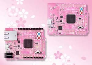
You can learn more about the GR-SAKURA from the following pages.
- About Gadget Renesas
- Reference
- Boards Distributor
RS Components
Element14
3. Waving the Fan
We will use a servomotor to drive the fan. Unlike most motor types, the servomotor allows precise control of where the motor stops. With a servomotor, the amount of rotor rotation is controlled by an input signal: the value of this signal “tells” the motor how far to rotate. The motor stops moving when it reaches the target position. The servomotor is widely used for radio control devices.
For this project, we will shall be using this servomotor.
https://www.gwsus.com/english/product/servo/micro.htm

Next, let’s look at the functions our gadget will need, and the way we will fit these together. After that, we will think more about the specific processing that each section will need to carry out.
Between Detection and Control: The Analog/Digital Converter
Let’s look first at the processing required to send information from the heartbeat detection section to the control section. The heartbeat sensor will output an analog signal, but the microcontroller (the control section) requires a digital signal. Accordingly, we will use an analog/digital converter (ADC) to convert the sensor’s analog output into the required digital signal.
An ADC carries out conversion in three steps: (1) sampling, where the ADC takes periodic readings (samples) of the signal; (2) quantization, where each reading is mapped to a discrete number that represents a close approximation of the signal level; and (3) encoding, where the discrete number is converted into a digital signal. (See Figure 2) An ADC with a sampling frequency of 10 Hz and a resolution of 10 bits, for example, will read the signal level 10 times per second, map each reading to one of 1024 numbers, and convert these values into the binary values carried by the digital signal.
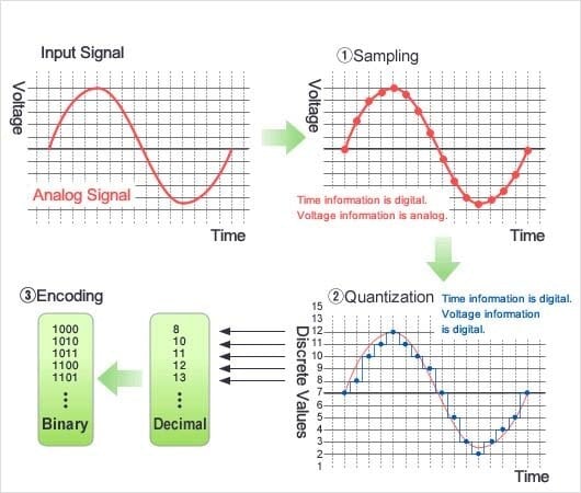
Figure 2: How an ADC Works
Most microcontrollers include built-in ADCs, among various other peripheral functions. The GR-SAKURA microcontroller includes two ADCs: a 10-bit ADC and a 12-bit ADC.
Between Control Section and Fan Section: PWM Control
Next, let’s look at processing required to control and drive the fan. The input signal into the servomotor will be a series of pulses, where the width of each pulse will determine how far the motor will rotate (the angle of rotation). For example, a narrow pulse will cause no rotation (0°), while a medium pulse will cause the motor to rotate by 90°.
To drive the servomotor, therefore, we send one pulse per period (per frame), where the width of the pulse tells the motor where to stop. If the pulse width remains the same on successive pulses, the motor will simply hold its position. In the case of our fan, for example, we might direct the fan to rotate from 0° to 60° and back to 0°, with the fan stopping at each position until the pulse width changes.
This type of control is referred to as pulse width modulation (PWM). The pulse corresponds to periodic HIGH output from the microcontroller. The microcontroller drives the motor by varying the duration of the HIGH level with each period (frame). (See Figure 3)
In most implementations, the pulse occurs at the start of the frame (at the point where the level changes from L to H). The “pulse width” refers to the duration of the H level, while the “frame” (or period) is the combined duration of the H and L levels.
For more information about PWM control, please refer to the manual for the servomotor we are using in this project. (Figures 4 and 5 are from the manual.) Source: RPV Servomotor Application Notes
https://www.gws.com.tw/english/product/servo/servo%20form.htm
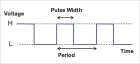
Figure 3: PWM
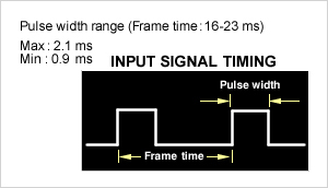
Figure 4: Pulse Width
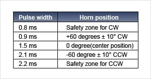
Figure 5: Target Angle
For this servomotor, the frame duration is 16 to 23 ms. Pulse width ranges from a minimum of 0.9 ms to a maximum of 2.1 ms (Figure 4). To move the motor to center position, we would hold the H level (within the frame) to 1.5 ms (Figure 5). To move the motor to the 60° position, hold the H level for 0.9 ms. To move the motor to the -60° position, hold the H level for 2.1 ms.
As you can see, the duration of the frames and pulses are the key to controlling the servomotor. You can also see that timing has to be controlled precisely, to within a fraction of a millisecond. The GR-SAKURA microcontroller includes a precision built-in timer that makes this possible.
As we conclude our first session, note that we still haven’t talked about the heartbeat sensor’s signal, or about how we will monitor the beat. But we do know that we will need to implement precise and defined timing control for both the input (heartbeat signal) and the output (pulse width).

In or next session, we will see how to use the GR-SAKURA. After that, we will explain the hardware, and then the software. We look forward to it.
These topics are covered in more depth in the following courses:
- Introduction to Digital Circuits — Part 1 (Explains the difference between analog and digital circuits).
- Introduction to Microcontrollers — Part 1 (Explains basic microcontroller functions and design)