Introductory Gadget Building: 4 of 4
In this final session of the Heartbeat Fan project, we will build the program that drives the servo motor in sync with the detected heartbeat. And then you can sit back, relax, and enjoy your fan for the rest of the summer.
Program Flow Diagram
In our previous session, we completed our hardware assembly. In this final session, we will create a program to control this hardware. Specifically, we need a program that detects the information coming from the heartbeat sensor, and drives the servo motor accordingly. We want the motor to drive the fan through one stroke for each heartbeat.
For each fan stroke, we want the fan to move to a preset angle (displacement) and then return. To avoid overstressing our servo motor, we will use an angle of 30 degrees. Note that the motor's specifications tell us that the motor takes 0.1 second to move through this distance.
Now let's see what our sensor's output looks like (Figure 1). The upper signal is from a normal heartbeat; the lower signal is from a more excited heartbeat. In both cases, the sensor shows fairly long intervals (troughs) of low voltage, punctuated by briefer periods (peaks) of high voltage. Let's call the peaks "R intervals", and the troughs "non-R intervals."
And let's write the program so that the servo motor turns 30 degrees when an R interval occurs, and then returns when the subsequent non-R interval occurs.
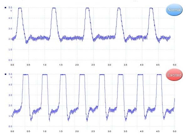
Figure 1: Heartbeat Data; Normal (above) and Excited (below)
The sensor output feeds into the A/D converter in the GR-SAKURA's microcontroller. We will consider that values at or above a certain threshold correspond to an R-interval. In our program, we will set the constant R_HEIGHT equal to this threshold. When the program determines that the input data has risen above this threshold, it will send a rotate instruction to the servo motor, causing the fan to move. When the program then determines that the input data has fallen back below this threshold (indicating the start of a non-R interval), it sends an instruction telling the servo motor to move the fan back.
Let's also remember that it takes the servo motor about 0.1 second to move through 30 degrees. Since we don't want to initiate a reverse movement during this time, we will write the program so that it will block out any other actions during this 0.1-second interval.
Figure 2 is a flow diagram for the required program. Flow diagrams help programmers and others understand what the program must do.
We have already written a program (source code) based on this flow.
Heartbeat Fan Program (source code): GR Sakura Source File (TXT)
In this series, we will not go into an explanation of the program. Instead, we will move right ahead to compiling the program and getting it to drive the fan. The program itself is a very simple one, however, and we encourage you to try writing your own program for it.
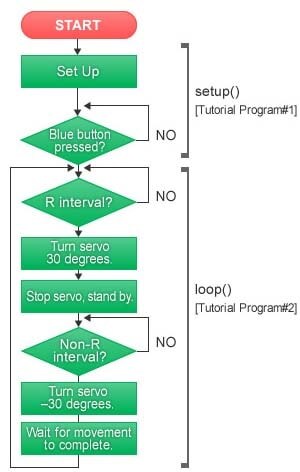
Figure 2: Program Flow for Heartbeat Fan
Easy Programming Using Our Online Library and Compiler
Our online compiler for the GR-SAKURA will allow us to make easy work of the required programming. First, we set up a new project, and name it "Heartbeat Fan." Please refer back to Part 2: A Closer Look at the GR-SAKURA Board, and Getting Ready.
Next, let's import the library that contains the program code we will use to drive the servo motor. Select Libraries from the menu bar along the top of the Web Compiler window, and then select the gr_sakura_servo library from the selection list, and click Import (Figure. 3). This tells the compiler that it must link in the servo-motor library when compiling the program (source code) into object code. Note that numerous libraries are available for use with the GR-SAKURA, enabling easy programming for a variety of projects.
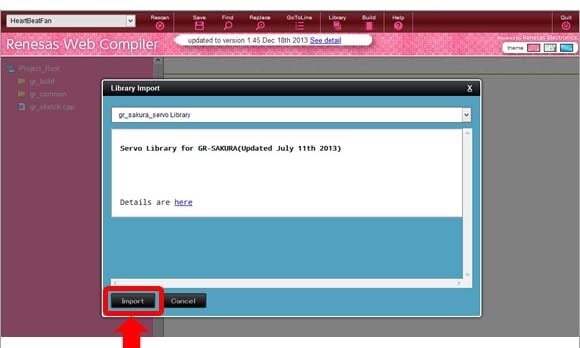
Figure 3: Importing the Servo-Motor Library
Now, let's proceed to create the program. Click gr_sketch.cpp (on the left side of the Web Compiler window), to open the source-code window shown in Figure 4.
When the source-code window opens, it shows sample source code that can be used to drive the GR-SAKURA's LEDs. We can now proceed to rewrite this source code to create the source code we need. In today's project, we can simply replace this code by cutting-and-pasting, or entering by hand, the Heartbeat Fan Program (source code) GR Sakura Source File (TXT) we prepared based on the flow diagram above. When you have finished, click the Save button to save the completed source code.
Next, click Build to start the compiler. If no error occurs, the compiler will create the object code and return it in a file named sketch.bin.
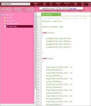
Figure 4: Program(source code) gr_scetch.cpp

Figure 5: Downloading scrtch.bin
Now you must download this sketch.bin file so that you can load it into your GR-SAKURA. Right-click the filename sketch.bin, and select Download (Figure. 5). Your browser will proceed to download the file into its regular download folder.
Turn On the Power, and You're Ready to Go
We're just about ready to start up the fan. Check over the hardware assembly, referring back to Part 3, to confirm that everything's ready. Connect the GR-SAKURA, the heartbeat sensor, the board, and the servo motor in accordance with the circuit diagram (Photo 1).
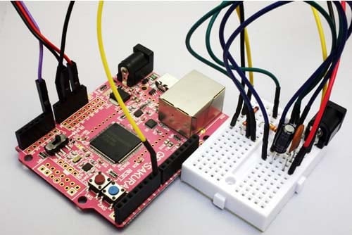
Photo 1: Wiring of GR-SAKURA and Board
Next, do the following (in the indicated order).
- (1) Connect the GR-SAKURA to your computer, using a USB cable. (This starts power supply to the GR-SAKURA.)
- (2) Connect the snaps from the battery box to the breadboard (This starts power to the breadboard.)
Note that you want to power-up the GR-SAKURA first, so that it will be able to protect the servo motor in the event that a problem occurs when power is supplied from the board into the motor. To ensure safety, this is the sequence you generally want to follow when building a project: first start power to the computer (in this case, the GR-SAKURA) that controls the power supply, and then start up the peripheral devices (in this case, the breadboard and the servo motor).
Next, go to your computer and drag the downloaded sketch.bin file into the GR-SAKURA (which is mounted as a drive). When loading is finished, the LEDs will be dark and the servo motor will start running. Now, use Velcro tape to attach the heartbeat sensor to your thumb. For best results, try winding the tape somewhat lightly but with full coverage, as if trying to block out all light from hitting the sensor.
Finally, place the fan (secure the motor) in an appropriate location, and then press the blue button on the GR-SAKURA. If everything is working as expected, the LED lighting will flash and the fan will move in time with your heartbeat—and the breeze will blow.
When you are ready to stop the fan, press the red button. When you are ready to completely shut down, cut the power to the board and then disconnect the USB cable. When shutting down, you want to shut off power to the peripherals before shutting off power to the controller (the reverse of the startup sequence).
We hope that everything has worked out—and that your fan moved as expected, in sync with your heartbeat. The program was written so that the fan rate would rise and fall together with changes in your heart rate (up to a maximum speed of 120 cycles/second).
We often hear about beginners who seem interested in these types of projects but are put off by perceived difficulties. In the past, perhaps, many of these projects lacked beginner-friendly explanations, and presented too many hurdles for inexperienced gadget-builders. But things become much easier when robust support is available, and when project-oriented boards like the GR-SAKURA are used. We encourage all beginners to try their hand at some of these challenges.
Tutorial Program#1
The setup() function sets up the input/output port(s), sets the input-voltage range for the A/D converter, and performs other essential initialization. Since in this project we wanted to also have a lamp flashing in sync with the heartbeat, our setup() function includes code that defines LED0 as an output destination. This function also defines PIN_SW input to enable the blue button to operate as a start switch, sets the initial servo motor position to 75 degrees, and then enters a standby loop that monitors the blue-button value until detecting that the button has been pressed.
Tutorial Program#2
The loop() function detects heartbeats; and, when a beat occurs, drives the fan accordingly. It uses two functions to carry out detection: rPulseDetect() watches for R intervals, and nonRDetect() watches for non-R intervals. Each function, upon detecting the start of the corresponding interval, monitors the duration of the interval and returns the result (in ms). Each return value is then passed to the fanservo.write() function, which drives the motor accordingly. The delay() function ensures a minimum interval between successive movements of the fan.

This completes our four-part introductory gadget-building project. We hope you enjoyed the experience of creating a working, functional device. We look forward to presenting more gadget-building projects in the future.
Module List
- What Does It Have to Do?
- A Closer Look at the GR-SAKURA Board, and Getting Ready
- Assembling the Hardware
- Creating the Software, and Completing the Project!
