Essentials of Microcontroller Use Learning about Peripherals: 2 of 6
This series explains peripheral MCU capabilities that are essential for the effective use of MCUs. For our hands-on work, we use the RX63N MCU mounted on the Renesas GR-SAKURA board. The sample program code comes from the GR-SAKURA software library.
Easy Programming Using MCU Timers
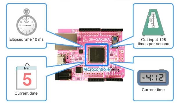
Microcontrollers (MCUs) are expected to know the current date and time. They are also frequently required to measure out predetermined time periods, and to track lapsed time. A typical application, for example, may repeatedly ask the MCU how much time has passed since the application itself started. Another application may instruct the MCU to issue a particular signal 128 times each second. Programs will also frequently tell the MCU to wait some specified amount of time before taking some further action or transitioning to some other process. In each of these cases—and in many others, too—the MCU must make use of one or more timers. These timers are typically implemented as peripheral functions on the MCU itself. (See Figure 1)

Figure 1: Types of Processing that Utilize a Timer
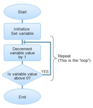
It's true, of course, that software can control wait-time on its own—without relying on the service of hardware timers—simply by keeping the CPU occupied with non-productive steps. This approach is illustrated in Figure 2. If we assume that the CPU takes 1 μs (microsecond; one-millionth of a second) to execute one iteration of the loop, we can effectively implement a 1-second wait by setting the initial value to 1 million and then looping one million times. One major problem with this approach is that it monopolizes the CPU, which is so busy counting to a million that it can't do anything else. Another problem is that you cannot freely set count customized increments; whereas timers support a wide variety of increments; 0.1 s; 1/1024 s; etc.
Still another big problem with this approach is that it is dependent on the CPU clock speed; if the program is later run on different CPU having a different clock speed, then the wait time will change too. If the wait period takes 1 second when running on a 100 MHz CPU, it will take 2 seconds when running on a 50 MHz CPU. If you wish to keep the speed the same, then, you would need to modify the loop code for each machine you work with. This would take a lot of time, and would also be prone to many errors. Wherever possible, therefore, it is better to use hardware to keep track of time.

Figure 2: Software "Timer"
A Little Interruption About Interrupts…
Let's briefly introduce the concept of interrupts, which are an essential feature of hardware timer operation. An interrupt—as its name implies—interrupts current processing to request immediate handling of some other processing. By using interrupts, it is possible to get the CPU's attention even when the CPU is engaged in doing something else.
Here's an analogy from the kitchen. You're boiling some noodles, and you want to take them off the stove in exactly three minutes. One way to do this is to stand by and stare at the second hand on your clock for three minutes; this is the approach that software takes when it waits for a loop to repeat itself a million times. Another way is to set a kitchen timer, and then do something else until the alarm "interrupts" you and gets your attention back. With this method, you can work at other tasks freely until the interrupt comes along.
The various peripheral timers in the MCU alert the CPU when a predetermined time has been reached (lapsed time; time of day; time of completion; etc.) by sending interrupts. Such interrupts are used by many other peripherals, as well: for example, to inform the CPU that some monitored status has changed, or that some process has started or ended. The CPU can keep busy with other tasks until each interrupt comes along, so overall efficiency remains high.
In session 4 of this series, we will look more closely at interrupt processing and IRQs (interrupt requests). In this current session, we simply want to bring home the fact that interrupts are an essential modality by which peripheral functions communicate with the CPU.
Timers and Watchdogs
The peripheral timers most frequently used by MCUs are those that count out a specific time period, and those that issue periodic interrupts. The RX63N includes numerous other timers as well, including one that generates a PWM (pulse-width modulation) signal used for servo motor control, another that measures the time between input signals, and an RTC (real-time clock) that keeps track of the current time.
One of the more interesting timers in common use within embedded systems is the "watchdog" (WDT: watchdog timer), also known as the "cop" (computer-operating-properly) timer. As both of its names imply, this timer's role is to detect and respond to computer malfunctions, so that the system can recover from runaway programs that would otherwise cause it to freeze. When the system starts a program, it also writes a predetermined time count into the WDT. The WDT then automatically decrements the count periodically. If the program reaches its end normally, it clears the WDT count value just before closing. If the program hangs, however, the WDT count will continue decrementing. When the value drops below 0 (an "underflow" condition), the WDT will generate an interrupt alerting the CPU that an error has occurred. WDTs are extremely important in systems that must not be permitted to freeze—and, in particular, in systems (such as embedded systems) where users cannot easily act to reset the system themselves.
Hands-On!
Before we can write a program to control timers on any given MCU, we would need to read through the MCU documentation for crucial information about the hardware's specifications, the peripherals' specifications, the appropriate program flow, and more. Fortunately, we can avoid these difficulties today by using the Renesas programming library. The library includes code specifically written to control time-related functions on the GR-SAKURA-mounted RX63N. The library can be accessed through the link immediately below.
SAKURA Sketch Reference: Sakura Time Library
Our hands-on program will continuously flash one of the LEDs on the GR-SAKURA board: 1 second on, 1 second off, repeat. This is a very simple program, but it still requires the use of a timer to measure elapsed time in order to accurately control the blink rate. Fortunately, the "time' section of the library includes program code that can use a timer for just this purpose.
The program code is shown in Figure 3. The millis function in line 14 returns the amount of time that has passed (in ms, as an unsigned long integer) since the program started. Note that this function does not take any arguments. As the program loops, it continues to get new values for the elapsed time, so that it can determine when 1 second has elapsed, and then when 2 seconds have elapsed. The wait is implemented with a while statement, and the variable a is used to implement the 1-second waits (lines 15 and 19). The program operates on "LED0", which corresponds to D1 on the board. The program turns the light on after 1 second has passed, then off when 2 seconds have passed. It then repeats.
| 1 2 3 4 5 6 7 8 9 10 11 12 13 14 15 16 17 18 19 20 21 22 23 | #include <rxduino.h> #define WAIT_TIME 1000UL void loop() { pinMode( PIN_LED0, OUTPUT); { void loop() { unsigned long a; a = millis(); //Get time since program start while( ( millis() - a) < WAIT_TIME) { } //Wait 1 second digitalWrite( PIN_LED0, 1); //Turn LED on while( (millis() - a) < WAIT_TIME + WAIT_TIME) { } //Wait another second digitalWrite( PIN_LED0, 0); //Turn LED off } |
*Text following "//" is a comment, and does not affect the execution of the program.
*The purpose of this program is for understanding the principle. It is not a rigorous implementation.
Compile the code using the online compiler, and transfer the resulting binary file into the GR-SAKURA board. The board will respond by turning off all four LEDs and then starting execution. As execution continues, LED0 (LED D1 on the board) will continue to flash: 1 second on, 1 second off, repeat.
This completes our hands-on introduction to peripheral timers, which are essential to the effective operation of MCUs. Time-related processing is used for a wide variety of purposes, and we invite you to try out some of the other programming code in our library.
Earlier in this article we mentioned that a program might want to get input 128 times per second, or to control timing in increments of 1/1024 seconds. If you thought that these numbers seemed like random, arbitrary examples—they are not. They are simply powers of 2: 128 is the 7th power, and 1024 is the 10th. Powers of 2 are ubiquitous in the word of programming and MCUs.
In our next session, we will look at another major peripheral: the UART (universal asynchronous receiver/transmitter). We look forward to seeing you then.