Essentials of Microcontroller Use Learning about Peripherals: 4 of 6
We continue our series on the implementation and use of the peripheral capabilities that support microcontrollers (MCUs). In this session we look at interrupts—one of the most fundamental approaches to effective MCU use.
What Is an Interrupt?
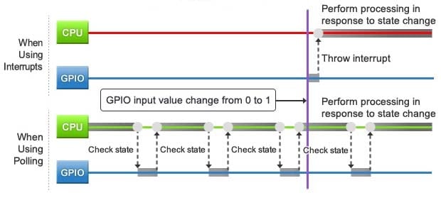
We introduced the concept of interrupts in the second session of this series, in our discussion of timers. Consider now a similar analogy to illustrate how things might work without an interrupt: if you are boiling eggs, and you want to take them off the stove in 10 minutes, then one way to do it is to check the clock every now and then to see if the time is up. The same is true in embedded systems: if you want to wait for a specific state change to occur before doing some operation, then one way to do this is to periodically check the state. Or again, if your program is waiting for a GPIO input level; to change from 0 to 1 before executing some step, then one way to proceed is to periodically check the GPIO value. This approach—periodic checking—is referred to as polling.
While polling is a simple way to check for state changes, there's a cost. If the checking interval is too long, there can be a long lag between occurrence and detection—and you may miss the change completely, if the state changes back before you check. A shorter interval will get faster and more reliable detection, but also consumes much more processing time and power, since many more checks will come back negative.
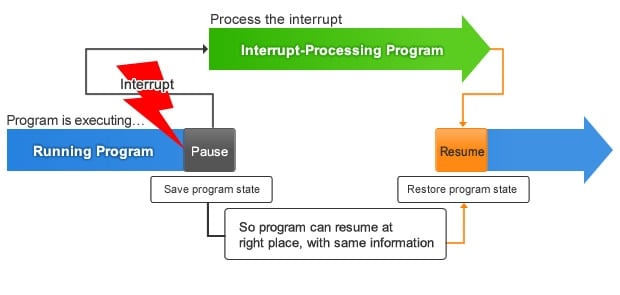
An alternative approach is to utilize interrupts. With this method, the state change generates an interrupt signal that causes the CPU to suspend its current operation (and save its current state), then execute the processing associated with the interrupt, and then restore its previous state and resume where it left off. (See Figure 1)

Figure 1: Interrupts vs. Polling
Let's go back to the boiling-eggs example. Instead of checking periodically, we will just set a timer for 10 minutes, and do something else until the timer rings, turning our attention back to the eggs. In this case the timer is working as an interrupt, and "taking the eggs out of the pot" is the associated processing.
How an MCU Processes Interrupts
Interrupts can originate from both MCU-internal and MCU-external devices. An interrupt from an external switch or sensor, for example, is sometimes called "attached interrupt", as it is generated by an external device that is attached to an IRQ (interrupt request) pin on the MCU. When the relevant state change occurs, the external device sends an interrupt request signal to this pin, and this in turn generates a notification to the MCU's interrupt controller (on the RX63N, this controller is called the "ICUb").
In contrast, interrupts from on-chip peripherals—internal timers, GPIO lines, UARTs, etc.—are referred to as "peripheral interrupts." These interrupt signals generate direct notification to the interrupt controller, with no need for pin attachments.
The interrupt controller's job is to pass these interrupt requests to the CPU in a coordinated way. When multiple interrupts occur, the controller must send these to the CPU in the appropriate order, based on their relative priorities. And the controller must also be aware of which interrupts are currently masked (disabled), so that it can ignore these interruptions completely.
When the CPU receives an interrupt request from the controller, it stops executing the program it is working on, and automatically saves all of the relevant working information so that it can later resume from where it left off. It then loads and executes the interrupt processing program that corresponds with the interrupt request that it received. After completing this processing, the CPU restores the saved information and resumes from where it stopped. (See Figure 2) Note that saving and resuming are handled automatically by the CPU; programmers need not concern themselves with these details.

Figure 2: Interrupt Processing Flow
Consider the case of serial communication through a UART. It would be inefficient to periodically monitor the UART for the arrival of a new character. In most cases, therefore, the system is designed so that the UART itself will generate an interrupt when a new character arrives, alerting the CPU to carry out the appropriate processing.
Similarly, internal timers are often set up to drive interrupts to repeatedly execute some particular process at some specific interval: each time the interval elapses, the timer generates an interrupt that tells the CPU to run that process. In general, the use of these types of interrupts can greatly increase the efficiency of MCU operation.
Interrupt Programming is Difficult—Except When You Use the Library!
To write an interrupt program from scratch, the programmer would first require a deep understanding of the target MCU's specifications. Programs would have to be customized to each MCU, and would be quite a chore to code. Using existing program code from the library, however, makes everything easier. The GR-SAKURA includes an interrupt library that makes it very easy to set up processing for attached interrupts. So let's try it.
SAKURA Sketch Reference: Sakura Interrupt Library
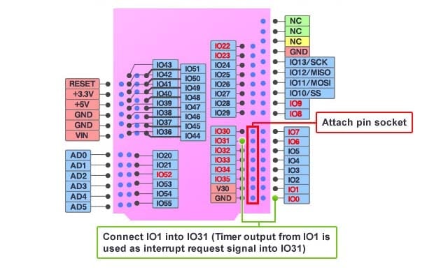
Before we can use attached interrupts on the GR-SAKURA board, we must first make the physical attachments. The GR-SAKURA is designed to accept interrupt signals into pins IO30 to IO35. For our sample program we will output a timer signal from pin IO0, and use this as an interrupt signal into pin IO31. So let's first attach a pin socket into the pin row running from IO30 to GND, and then let's run a breadboard wire to connect IO0 to IO31. (See Figure 3)

Figure 3: GR-SAKURA Setup (Pin Arrangement)
Our sample program (Figure 4) will cycle through on-board LEDs, causing the next LED to light up each time the input into interrupt pin IO31 changes from L to H. As explained earlier, input into this pin causes the CPU to execute the corresponding interrupt processing.
Note: The compiled program will only work if IO0 and IO31 are connected by wire, as explained above.
| 1 2 3 4 5 6 7 8 9 10 11 12 13 14 15 16 17 18 19 20 21 22 23 24 25 26 27 28 29 30 31 32 33 34 35 36 37 38 39 40 41 42 43 44 45 46 47 48 49 50 51 52 53 54 55 |
/*GR-SAKURA Sketch Template Version: V1.08*/ #include <rxduino.h> #define INTERVAL 1 int i = 0; void irq3() //Start this function when interrupt arrives at pin IO31; it turns each LED on and off in succession { switch( i) { case 0: digitalWrite( PIN_LED3, 0); //Turn off LED3 digitalWrite( PIN_LED0, 1); //Turn on LED0 i++; break; case 1: digitalWrite( PIN_LED0, 0); //Turn off LED0 digitalWrite( PIN_LED1, 1); //Turn on LED1 i++; break; case 2: digitalWrite( PIN_LED1, 0); //Turn off LED1 digitalWrite( PIN_LED2, 1); //Turn on LED2 i++; break; case 3: digitalWrite( PIN_LED2, 0); //Turn off LED2 digitalWrite( PIN_LED3, 1); //Turn on LED3 i = 0; break; } } void setup() //Set output destination pin, LEDs initial state (all off), function to be invoked by interrupt, and timer interval { pinMode(PIN_LED0,OUTPUT); //Set GPIO to output to LED0 pinMode(PIN_LED1,OUTPUT); //Set GPIO to output to LED1 pinMode(PIN_LED2,OUTPUT); //Set GPIO to output to LED2 pinMode(PIN_LED3,OUTPUT); //Set GPIO to output to LED3 pinMode(PIN_P21, OUTPUT); //Set IO0 pin (timer output) to output mode digitalWrite( PIN_LED0, 0); //Turn off LED0 digitalWrite( PIN_LED1, 0); //Turn off LED1 digitalWrite( PIN_LED2, 0); // Turn off LED2 digitalWrite( PIN_LED3, 0); // Turn off LED3 attachInterrupt(3, irq3, RISING); //Call irq3() when IO31 (IRQ3) interrupt is received tone(PIN_P21, INTERVAL, 0); //Output from IO0 at interval set by INTERVAL } void loop() // No processing inside loop() { } |
Figure 4: Sample Program Demonstrating External Interrupts
*Text following "//" is a comment, and does not affect the execution of the program.
*The purpose of this program is for understanding the principle. It is not a rigorous implementation.
This program defines the processing to be carried out when an interrupt is received at the designated interrupt pin. Specifically, the designated interrupt is generated each time the input level into pin IO31 changes from L to H. The attachInterrupt() function, at line 48, is used to assign interrupt programs to interrupt pins—telling the program which interrupt function to call in response to state changes at each pin. In this program, attachInterrupt() sets the program to respond to the interrupt signal received at IO31 by calling irq3(). Note that all initial settings are made by the setup() function: this function calls the attachInterrupt() function, and also defines the timer, designates the timer output pins, and sets up LED outputs.
Note also that loop() does not itself execute any processing. Instead, all of the work is carried out by irq3(). The program itself does not contain code that calls this function; rather, this is the interrupt function that is called to drive the LEDs each time an interrupt is received at IO31. When the program starts, all four LEDs are off; then when the first interrupt occurs, irq(3) turns on LED0; thereafter, each new interrupt causes irq(3) to turn off the currently lit LED and turn on the next one, in a continuous cycle (LED 0 to 4, and repeat). Only one LED is lit at any given time. The case statements define this cycling action: at each new interrupt, irq3() uses GPIO output to turn off the currently lit LED and cycle to the next one.
Interrupts are especially effective for handling events that can occur at unexpected times. In general, they also help eliminate inefficient program operation, and this in turn helps reduce power consumption. The appropriate use of interrupts is absolutely essential to achieving effective use of MCUs.
In our next two sessions, we will look at how programs actually work—at how they behave, and at how this behavior relates to the hardware. These two sessions should help to further clarify the program examples and hardware explanations that have appeared so far in this series.