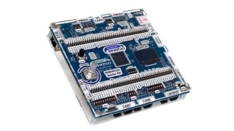
Vehicle Control Unit

Overview

Description

The Vehicle Control Unit (VCU) solution facilitates the implementation of a Software Oriented Architecture (SOA) or Software Defined Vehicle (SDV). The necessary interfaces such as standard and Gigabit Ethernet (GbE) are present to support zonal architecture by OEM.

Additionally, in entry-level/commercial vehicles, this VCU can act like a central compute/gateway, as the RH850/U2A automotive-control MCU device has sufficient performance headroom with multi-core architecture compliant with Functional Safety (FuSa) ASIL-B to ASIL-D.

System Benefits​:

  • Hardware design files and sample software are available.
  • A wireless communication board (REIN-WCB-V1) can be added to this solution enabling connected vehicle technology including 4G/GPS/Wi-Fi/Bluetooth® Low Energy (LE).
  • "No Wait" Over-the-Air (OTA) updates supported by the RH850/U2A MCU.
  • The onboard embedded Multi-Media Card (eMMC) provides Large Storage for various use cases.

Comparison

Applications

  • Passenger and commercial vehicles

Winning Combinations Interactive Diagram

Select a block to discover products for your design

AS260 Main Connector AS260 AS260 AS260 DC/DC 1 DC/DC DC/DC DC/DC 2 DC/DC DC/DC Buffer x4 Buffer x4 Buffer x4 Buffer x4 Buffer x4 Buffer x4 Buffer x4 Gyro Gyro Gyro I/O Connector Ethernet Ethernet Ethernet Gb Ethernet Gb Ethernet Gb Ethernet eMMC eMMC eMMC NOR Flash NOR Flash NOR Flash Communication Card Connector Connector Arrow Connector Arrow.182 Connector Arrow.183 Connector Arrow.187 Sheet.200 Right arrow 1pt.1045 18 18 18 Sheet.195 Sheet.201 Right arrow 1pt.1045 7 7 7 Sheet.204 Sheet.205 Right arrow 1pt.1045 11 11 11 Sheet.208 Sheet.213 Right arrow 1pt.1045 2 2 2 Sheet.216 Sheet.217 Right arrow 1pt.1045 4 4 4 Sheet.220 Sheet.221 Right arrow 1pt.1045 4 4 4 Sheet.224 Sheet.225 Right arrow 1pt.1045 4 4 4 Sheet.228 4 Right arrow 1pt.1045 4 4 4 Sheet.232 Sheet.235 Right arrow 1pt.1045 2 2 2 Sheet.238 Sheet.239 Right arrow 1pt.1045 4 4 4 Sheet.242 2.243 Right arrow 1pt.1045 2 2 2 Sheet.246 8.247 Right arrow 1pt.1045 8 8 8 Sheet.250 12.251 Right arrow 1pt.1045 12 12 12 Sheet.254 Sheet.255 Right arrow 1pt.1045 16 16 16 Sheet.258 Buffer x4 Connector Line 12V Input 12V Input 12V Input 3.3/3Amax 3.3/3Amax 3.3/3Amax 1.09V/2.5Amax 1.09V/2.5Amax 1.09V/2.5Amax 3.3V 3.3V 3.3V Right arrow 1pt.1045 2 2 2 Sheet.275 Right arrow 1pt.277 3 3 3 Sheet.279 Right arrow 1pt.281 12 12 12 Sheet.283 Right arrow 1pt.285 8 8 8 Sheet.287 Right arrow 1pt.289 9 9 9 Sheet.291 RSENT RSENT RSENT PSI PSI PSI MSPI x3 MSPI x3 MSPI x3 Voltage, Current Sense Voltage, Current Sense Voltage, Current Sense HS/LS Switch Signal HS/LS Switch Signal HS/LS Switch Signal I/O Connector I/O Connector I/O Connector Communication Card Connector Communication Card Connector CommunicationCard Connector Ignition Sense Ignition Sense Ignition Sense ISO CAN x2 ISO CAN x2 ISO CAN x2 LIN x2 LIN x2 LIN x2 CAN x2 CAN x2 CAN x2 Main Connector Main Connector Main Connector MCU MCU MCU MCU VCC VCC VCC ISO ISO ISO GPIO 1 GPIO GPIO SPI 1 SPI SPI ADC ADC ADC I2C I2C I2C ETNBO ETNBO ETNBO ETNB1 ETNB1 ETNB1 CAN 2 CAN CAN GPIO 2 GPIO GPIO CAN 1 CAN CAN LIN LIN LIN SFMA SFMA SFMA UART UART UART SPI 2 SPI SPI
Exiting Interactive Block Diagram