Radar Transceivers: Key Components for ADAS & Autonomous Driving
- Blog 1: Why Do We Need Radar?
- Blog 2: Basics of FMCW Radar
- Blog 3: Radar Range: How Far Can a Radar "See"?
- Blog 4: Radar Resolution: How Accurate Can a Radar Be?
- Blog 5: Radar Architecture: How to Connect Different Radar Sensors
- Blog 6: How to connect the antennas?
- Blog 7: Antennas for Automotive Radar
Architecture Evolution
In previous issues of the radar blog, we have addressed how the number of sensors in general and radar modules, in particular, will be dramatically increased to achieve higher levels of autonomy and safety. In the next years, radar modules will be added to go from a basic configuration, with only a forward-looking radar with level L1 autonomy and 1 to 4 NCAP (new car assessment program) rating to up to level L2+ autonomy and NCAP 4-5 in standard cars and levels L3-L4 of autonomy and NCAP 5 in the premium segment, as shown in Figure 1.

Figure 1. Automotive radar for different NCAP and levels of autonomous driving
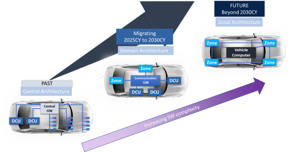
The performance of the central computing units is expected to grow at a rapid pace with the centralization of the vehicle’s functions. Therefore, the processing of the data can be carried out in a more efficient way if the computation is not directly performed in the sensor modules. This leads to an evolution in the car E/E architecture to a distributed architecture. Of course, the migration to the fully distributed architecture will take a long time and is expected to be completed after 2030. But until then, some partial implementations will appear in the market.
As a first step, some domain controllers are for specific functions such as ADAS. Then the number of domain controllers will increase along with the level of autonomy of the car. With requirements for level L2+ of autonomy, zone controllers will be introduced along with the domain controllers, leading to the final step, centralized E/E architecture with the vehicle's central computer connected to the sensors through the zone control units. This evolution is illustrated in Figure 2. Of course, this will also be coupled with an exponential increase in software complexity and will require high-capacity networking in the vehicle.
Figure 2. E/E architecture mega trend (source: David Xu, Renesas Electronics)
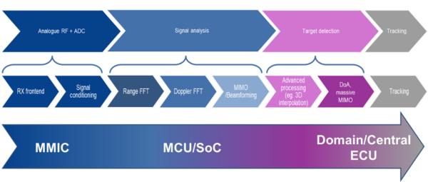
With the new E/E architectures being introduced, part of the radar processing shown in Figure 3 will not take place on the radar module (edge computing) but will instead be delocalized for more efficient computations. The amount of processing in each module or control unit will be determined by the desired performance and by the available architecture.
Figure 3. Radar processing steps
Smart Radar Sensors
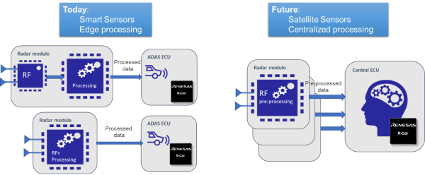
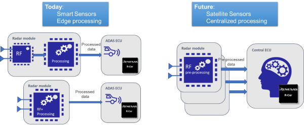
Today’s radar architecture is based on a set of separate radar modules distributed around the vehicle. Each module has its own radar transceiver and the capability to process the detected data on board, either using a single chip or with a separate microcontroller or SoC on the same module, as shown in Figure 4.
Figure 4. Smart sensors with edge processing
The processed radar data are then transferred from each “smart radar sensor” to a remote domain control unit for further processing and fusion using a CAN bus. The different processing steps and where they are performed are illustrated in Figure 5.

Figure 5. Radar signal processing with smart radar sensors and domain control unit
If enough sensors are used, the obstacles in the environment of the vehicle can be identified. For example, in the case shown in Figure 6, the ADAS ECU will receive the information of the objects detected by the forward-looking long-range radar, and from four corner short- and mid-range radars, to create the full image of the surroundings.

Figure 6. Example of radar architecture with smart sensors (edge processing) and domain controller
Satellite Radar Sensors
With the introduction of centralized computing architectures, in the future, the processing of the data from some radar modules could be de-localized. The radar modules themselves would then be less “smart”: now these satellite radar units will be able to perform a limited amount of processing of the received radar signals, for example, the range-FFT, before transferring the data to a remote ECU (either a domain or a zone controller), as shown in Figure 7.
Figure 7. Satellite sensors with central processing
The ECU will then receive the pre-processed data from the different satellite radar modules and perform the main radar processing steps for each set of data. The obtained results can then be fused together, or combined with the information obtained from other sensors, to increase the accuracy of the detection. The different steps are illustrated in Figure 8.

Figure 8. Radar signal processing in satellite radar and central ECU
In the first implementations of this centralized architecture with satellite radar modules, the data will be transferred to the ECUs using the vehicle’s Ethernet backbone. For some applications such as forward-looking radar or imaging radar, which require a large amount of radar, smart sensors will still be used, with full radar processing still being performed at the edge. On the other hand, several satellite radars will be distributed around the vehicle to provide 360° awareness of the surroundings. For example, in the architecture depicted in Figure 9, the data acquired by the corner and ultra-short-range radars will be pre-processed, possibly compressed, and then sent to the zone ECU for further computation.

Figure 9. Example of radar architecture with satellite modules and remote processing on zone-based ECUs
The use of satellite radar modules with a centralized processing architecture offers a wide range of benefits.
On the one hand, the satellite radar modules become simpler, thus saving size and cost. They are also easier to repair and upgrade when necessary. The problem of heat dissipation is also reduced, especially for the modules placed close to other vehicle elements that can reach high temperatures, such as headlights.
By using the ethernet backbone of the vehicle for the data transfer the cost and the weight of the cabling can be optimized. Of course, security measures will have to be implemented for ethernet transmission. And now, the data will be in a format that is easy to store and process along with those from other sensors.
Using the vehicle’s control units for the processing allows not only for much more efficient processing of the radar data but also for more complex operations. Data fusion with other sensor like cameras or LiDAR, machine learning and artificial intelligence can now be used to optimize the sensing and characterization of the environment, which will contribute to achieving higher levels of autonomous driving.
Comparison & Conclusions
In the future, the E/E architecture of the vehicles will evolve towards centralized computing solutions. For some years, different architectures will coexist, with both smart sensors and satellite radar modules being used. The main differences are summarized in the following table.
Table 1. Smart sensors vs. satellite sensors
| Radar Module | "Smart Sensor" | Centralized (Satellite) | |
|---|---|---|---|
| Processor location | Radar module/chip | Zonal/Central ECU | |
| Radar output | Processed data (objects) | Processed data (point cloud) | Raw data/Range FFT |
| Network type | CAN | 100Mb Ethernet | Gb Ethernet |
As mentioned before, the migration towards centralized architectures with higher computing performance will require that high-speed links be available throughout the vehicle. In the near future, the architecture will rely on the Ethernet backbone of the vehicle. Yet, alternatives like the use of MIPI A-phy are being considered for future radar generations.
Renesas is working towards providing cutting-edge solutions for future vehicles, with ECUs based on the R-Car Gen4 series and innovative components for both smart radar and satellite radar units.
Winning Combinations
News & Additional Resources
| Title | Type | Date |
|---|---|---|
| Renesas Unveils First Family of Automotive Radar Transceivers with Industry’s Highest Accuracy and Lowest Power Consumption | News | Nov 16, 2022 |


