In the previous blog in this series, we looked at the differences between the idealized digital world and the real world we must design for, and looked at the various types of noise we need to manage. In this blog, we’ll look at some of the typical noise sources that we can come across. These sources can be both external to our system and internal.
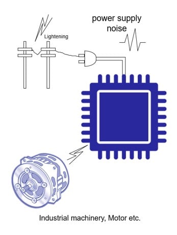
External noise sources are often one of the biggest threats to a system operating reliably, and there can be many sources of noise that we have to manage in our environment. These can include, Switching noise from a power supply, noise caused by sparks from Industrial machinery, Motors, etc., Induction noise from Relays, Transformers, Buzzers, Fluorescence lamps, etc., static discharges, typically from the body of users but also from elsewhere, and of course lightning.

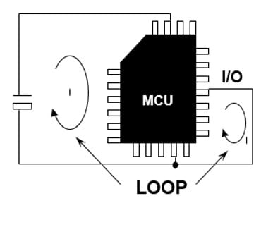
Internal noise can come from a wide variety of sources. Current loops on your PCB can be a significant source of radiated noise. If current flows in a closed loop formed by the MCU and its I/O signals, as shown in the diagram below, this current loop can act like an antenna, and significant noise can be radiated, especially if the current is large.

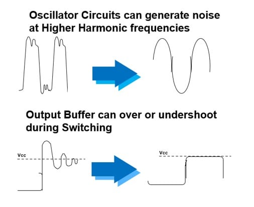
If you have a badly designed ground plane, where there is a voltage difference between the ground on different parts of the PCB, current can flow between these ground points; this act like an antenna, and noise can also be radiated. Other internal sources of radiated noise can include badly designed oscillator circuits. We always suggest you discuss using a specific oscillator with the oscillator manufacturer to ensure it will have stable performance in your system, and that you follow the recommended circuit parameters and ground plan positioning. This is especially important as not only will a badly designed oscillator inject noise into many parts of the circuit, especially the ground, but a badly designed oscillator circuit can also cause the device to fail.

Another common area where internal noise can be created is in the I/O system, especially if you are using multiple high-speed devices on an external bus. A badly designed I/O system, where care is not taken to avoid over or undershoot, can cause devices to exceed their electrical specification, and this can damage devices over time, causing failure, as well as increase the power consumption of the system and radiate noise into the rest of the system.
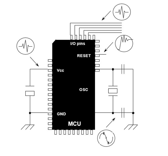
While today’s microcontrollers, such as the devices in the RA and RX microcontroller families, have circuitry designed to avoid Latch-up, it’s still good practice to avoid the potential for this condition. Noise can affect any pin of a typical microcontroller. However, microcontrollers systems pins are particularly sensitive to noise, as these pins typically control the fundamental operation of the device, and a failure induced by noise here could cause the device to malfunction. So special care should be taken to make sure the possibility of noise interfering with the normal operation of the system pins is minimized.

Systems pins on a typical microcontroller can include the reset pin, the power supply pins, the oscillator pins, and the mode or special function pins. To minimize the chance of noise disturbing these pins, we should take special care, making sure the power supply pins have solid voltage levels with the required filtering and that the ground plan doesn’t have any current loops, we should make sure the oscillator is placed as close to the chip as possible, and the PCB layout follows the recommendations of the supplier, and that the reset pin is protected from fast transient signals.
In the next blog in this series, we will look at some of the design techniques that can be used to minimize and protect microcontroller-based systems from noise.
Related Blogs
Reducing Noise Issues in Microcontroller Systems - Part 1
Reducing Noise Issues in Microcontroller Systems - Part 3
Reducing Noise Issues in Microcontroller Systems - Part 4
