Historically, servers aggregated timing onto a system board. Modern servers more commonly modularize the function and migrate the devices to different racks, like the tray of CPU, SSD, GPU, Accelerator, DRAM cards, etc., depicted in Figure 1.
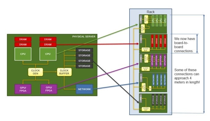
Power cycling the system is a desirable capability, but in a disaggregated system, aligning both input signal and power sequences across the entire system becomes more complicated. Ideally, the system powers up consistently; but in practice, the time delta between power on and output clocks being ready to turn on varies. Let’s walk through some example cases relating to system clock design:
Case 1: No VDD
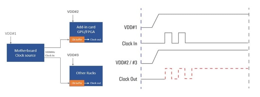
Figure 2 depicts a scenario where the motherboard sends its clock to other racks and add-in cards before power is ready. The clock buffers on the receiver side may start receiving the clock signal before their VDD turns on, thus outputting bad clock signals.
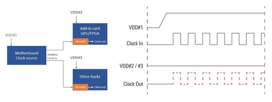
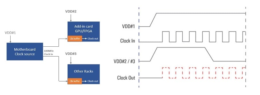
Figure 3, depicts a scenario where the clock chip powers down during operation due to emergency interrupts, like a system over-heat, hard reset, etc. A smart clock buffer can await a valid VDD prior to properly enabling the output.
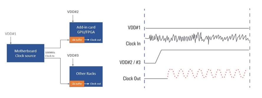
Case 2: Noise Drives Oscillation on the Clock Buffer Output
If an add-in card or rack on the clocking receiver side powers up first, those on the receiver side won’t necessarily wait for a good clock source from the main motherboard. If your clock inputs are not carefully designed, you may trigger ESD events, or clock buffer outputs may start oscillating in response to that stimulus. A smart clock buffer has a mechanism inside to monitor the valid input clock source.
Case 3: Leakage Issue
Another common issue is that the output of a clock chip stalls at high/low or low/high state when the input reference clock disappears. HCSL topology has a natural shutoff characteristic that uses a low/low state when they are disabled. For LPHCSL topology, this may cause a problem without synchronizing an input reference clock to OE, power good or power down pins. In these cases, the system is supposed to be powered down, but the clock output may still be driving at 850mV as shown in Figure 5. Such leakage will add unwanted heat to the CPU. Smart clock buffers can force the outputs to a low/low state when there is no signal on the input.
Helping customers address real world scenarios such as these helped us to define such a smart buffer. Renesas’ new PCIe Gen6 RC190024/20/16/13/08/04 clock buffer family and RC19216/08/04/02 multiplexer family have built-in features to overcome all of these scenarios, including passive features like Power Down Tolerance (PDT), Flexible Startup Sequence (FSS) and (Automatic Clock Park (ACP). All of this is transparent to system designers but makes avoiding all of these possible gotchas easy during the design process.
