Understanding the principle and application of high efficiency motors: 3 of 3
In our last two sessions we looked at some of the characteristics and advantages of BLDC motors. Small and efficient, these motors are an excellent choice for developers focused on delivering space-saving and energy-saving systems. One hurdle these developers face is the anticipated difficulty of implementing effective BLDC motor control. Renesas stands ready, however, with solutions that can greatly ease the process. In this session, we will actually control the BLDC motor using Renesas Solution Starter Kit "24V Motor Control Evaluation System for RX23T (hereinafter" Motor RSSK "). The motor RSSK is a set of inverter boards, control software and development support tools necessary for motor control.
Introduction to Motor RSSK
As we learned in the second session of this series, BLDC motor control requires the use of inverter circuitry together with an MCU capable of producing an appropriate PWM control signal. The Motor RSSK provides all of the essentials for implementing motor control, and is effectively an out-of-the-box solution. Users can freely download the related control software and development support tools from the Renesas website—making it easy for just about anyone to get some hands-on experience with various types of motor control method.
The kit presented here comes with an RX23T motor-control MCU, mounted on a CPU card that attaches to the inverter board. Other available CPU cards, with different MCUs, can be used in its place, allowing users to try multiple MCUs, and perhaps to choose from among them.
A variety of control software is available for use with Motor RSSK, providing support for vector control (Field oriented control), 120-degree conducting control, and more. In this session, we will try both 120-degree conducting control with Hall sensors, and sensorless vector control. Let’s begin with 120-degree conducting control.
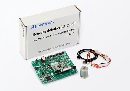
Figure 1: Motor RSSK (Renesas Solutions Starter Kit)
Motor Control Setup: The Analyzer Function
As we’re starting with 120-degree conducting control, we must first download the “Hall 120-degree Conducting Control” software from the Renesas website, and write it into our motor-control MCU. We will also need to download the Renesas Motor Workbench (RMW), a set of development support tools for motor control work. Please download the software from the following links.
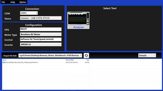
Figure 2: Renesas Motor Workbench: Initial Screen
The Renesas Motor Workbench (RMW) implements both “analyzer” and “tuner”. Let’s try the analyzer first.
One important advantage of the analyzer is that it allows the user to read and write MCU internal variables, and to view real-time waveform displays, with no need to stop the CPU or shut down the motor. This avoids the risk of damaging the inverter board with over current that might result if the CPU were to be stopped under certain PWM output conditions. This feature is particularly important in motor control applications. In the field of motor control, it is a very effective function because it can’t check the variables inside the MCU by breaking (stopping) the program like other applications. In addition, In the motor control method called vector control, the current value computed inside the MCU called "d axis" or "q axis" is used for control, but the value can’t be checked with the oscilloscope. It is also a big feature that it can directly check its current value.
Analyzer is ultimately an extremely useful motor-control development tool set, offering the capability to set triggers, zoom the display, and more. Since this function can be analyzed in real time, it is far more efficient than analyzing by outputting data to external memory using a DA converter or an external bus. Analyzer is also an user interface for motor control programs released in Renesas website and controls the motor movements by variables. Makes it easy for the user to utilize MCU variables to control the running and stopping of the motor.
Hands-On 120-degree Conducting Control
Now let’s use the analyzer to run the motor with 120-degree conducting control. For detailed instructions, refer to the kit’s user documentations, and to the application notes that come with the software.
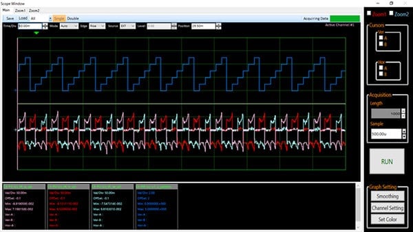
Figure 3: 120-degree Conducting Control Waveforms
(pink: phase U; red: phase V; pale blue: phase W) and Energizing Switching Signal ( blue)
The analyzer presents a waveform display such as shown in Figure 3, so that you can observe the waveforms for all of the phases. The center of the screen shows color-coded waveforms, and the lower part of the screen shows the corresponding data values. While there are certain moments when inverter-circuit switching makes current values inaccessible, the software does successfully display the characteristic waveforms. With 120-degree conducting control, we get rectangular current waveforms, such as those shown above. The energizing pattern switches in sync with the changes in the blue-colored signal.
Remember that, in our second session, we pointed out that 120-degree conducting control tends to produce some jerkiness in the motor movement. But observing the operation of the motor included in the kit, there is not so much unevenness. It is a small vibration that you do not know even if you touch it. It is also convincing that this control method is used in actual applications.
Vector Control Setup: The Tuner Function
Now let’s look at sensorless vector control. As with 120-degree conducting control, we have to write the control program into the RX23T CPU card. Two types of vector control programs are available: a web-based program that can be used as soon as the code is loaded into the CPU card; and a tuner-equipped control program that is downloaded together with the RMW. The tuner feature automatically adjusts the values of the motor parameters and control parameters required for vector control. Vector control requires a large number of parameters. The tuner can greatly simplify the task of setting the values correctly.
Automatic tuning, however, is not required if you are using the web-based program, as the program has already been adjusted to work with the motor that comes with the kit. While the web-based program would be fine for our tryout of vector control, we will use the tuner feature here, so that we can see how it works. The tuner-equipped program is downloaded as part of the RMW, and can be found in the mot_rmt folder of the RMW.
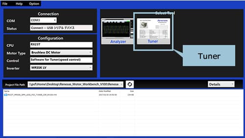
Figure 4: Screen When Using RMW with the Tuner-Equipped Vector Control Program.
When you use the downloaded program to connect to your tools, you can choose to run either the Analyzer or the Tuner.
Automatic Tuning of Motor Parameters
Vector control requires proper setting of numerous motor and control parameters. Although the precise number of parameters varies according to the control program being used, there are generally about 20.
The tuner feature greatly reduces the time required to adjust all of these values. When using the tuner, all you need to do is to connect up the BLDC motor you want to work with, and then enter the appropriate values for rated current, rated voltage, and number of pole pairs. The program will then automatically measure, calculate, and output the relevant parameter values. Simply load these values into your motor-control software, and the software will deliver stable motor control.
Operate the tuner function in accordance with the user documentation. It takes about 30 seconds to complete automatic parameter adjustment. You can then use the tuner to output the results to a definition file that can be used by the Renesas vector control program, or you can write the results into a PDF report (as in Figure 5). This is a very handy way to accumulate adjustment results without having to repeatedly adjust the same motor.
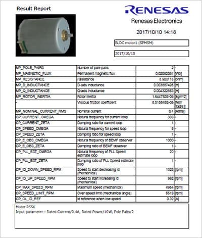
Figure 5: Parameter Display Generated by the Tuner Function.
The user enters the relevant values for rated voltage, rated current, and pole pair count, and the tuner automatically calculates the control parameters and displays them, as shown above.
Hands-On Vector Control
Now let’s use auto-adjusted parameter values to drive a BLDC motor by sensorless vector control—a method where torque is directly control to current. As we explained in the second session, vector control works by conversion of the coordinate space, with 3-phase AC values treated as 2-phase DC values. The two phases are the torque current component (q-axis current) and the excitation current component (d-axis current). The various phase waveforms can be viewed on the screen (Figure 6).
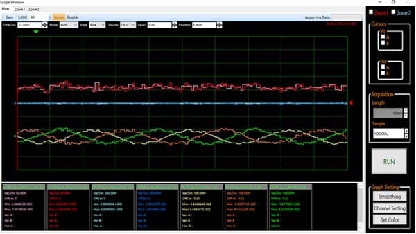
Figure 6: Vector Control: Current Waveforms
(red: q-axis current; blue: d-axis; yellow: phase U; orange: phase V; green: phase W)
The figure above shows the waveforms that result when we begin running the motor at 1000 rpm.
Check that the torque component (q-axis component, in red) is at about 50 mA.
Figure 7 shows what happens when we put a small load on the motor. As you can see, the d-axis current remains the same, while the torque component current (q axis) increase to about 100 mA. In other words, the torque rises in accordance with the load increase, without noticeable inefficiency. When we look at the corresponding 3-phase chart, we see that current to all three phases increases evenly. With vector control, the q-component current is changed as needed to output the torque that corresponds to the load; it would be much more difficult to achieve this by independently adjusting the current to the three phases. We can also see that, where the 120-degree conducting control produces relatively rectangular 3-phase waveforms, the waveforms with vector control are clean and sin wave. While the detailed differences may not be apparent from a simple viewing, the image does give the sense that vector control delivers smoother motor rotation.
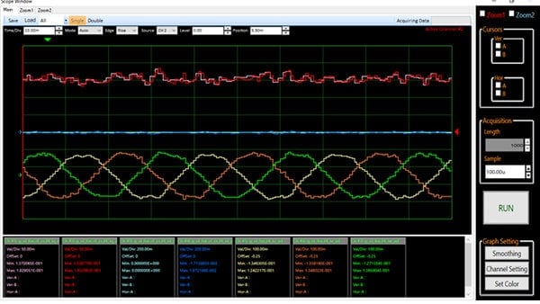
Figure 7: Waveform under Load
Give BLDC Motor Control a Try
In this session we saw how you can use the Renesas Solution Starter kit to try both 120-degree conducting control and sensorless vector control of a BLDC motor. The kit’s user documentation, and the software’s application notes, can help you go through these tryouts quickly and smoothly. Software has been provided for both control methods, so that users can compare the two methods and gain a deeper understanding of the principles involved in each case. This kit is highly recommended for anyone thinking about using BLDC motors in future applications.
For detailed information about how to set up the RMW and how to use the kit, you may want to view the videos available on the Renesas website. *You can purchase the RSS kit here.
Motor Control Evaluation System: Introduction and Start-Up
Conclusion
This is our third session in our series explaining BLDC motors. Unlike brushed DC motors—which are easy to connect up and run—BLDC motors require a bit more work. But they also offer the important advantages of high efficiency and small size. Their usage is already expanding in many areas of application, and these motors are likely to become increasingly mainstream going forward. Sensorless vector-control implementations, in particular, offer superlative efficiency together with the advantage of eliminating the sensor hardware—and are now gaining considerable attention for these reasons. While sensorless vector control is actually quite complicated, the Motor RSSK can greatly accelerate the implementation process. We encourage our customers, and prospective customers, to consider using Renesas solutions to facilitate the implementation of systems benefiting from small, efficient, and highly controllable BLDC motors.
Module List
- What are Brushless DC Motors
- Controlling BLDC Motors
- Renesas Solutions for BLDC Motor Control