In this blog, we introduce the RA6T2 evaluation environment, which enables operation check of BLDC motors with inductive position sensor IC (IPS2200).
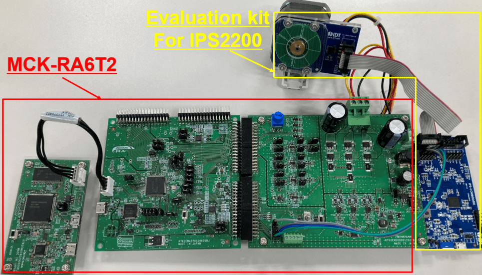
Two different RA6T2 evaluation kits are available as follows: (Figure 1)
- The MCK-RA6T2 Renesas Flexible Motor Control Kit with the RA6T2, which is an RA Family MCU specialized for motor control.
- The Evaluation Kit for IPS2200, which is an inductive position sensor IC.

The discussed application note and sample projects are available for download from the RA6T2 product page. Equipped with the evaluation kit and sample projects, you can seamlessly begin evaluation of a BLDC motor with inductive position sensor as shown in the video below. The evaluation environment and sample projects are also summarized in the application note that can be downloaded from the RA6T2 product page.
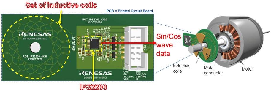
From here, the inductive position sensor will be briefly introduced. An inductive position sensor is a non-contact sensor that uses electromagnetic induction to detect the position of a motor. The sensing element uses a coil pattern layout on a printed circuit board as shown in Figure 2, and the position of the motor can be detected when a metal plate passes over this sensing element. This position information is output as sine and cosine wave data via the inductive position sensor IC.

The advantages of using this inductive position sensor include its functionality. The sensing element used in the inductive position sensor can be laid out with the same number of coil patterns as the pole pairs of the motor to be used (left side of Figure 3), so it can be adapted to a motor with various pole pairs. The coil substrate for the inductive position sensor can be mounted at the end or base of the shaft, providing high flexibility in designing motor machinery (right side of Figure 3). Furthermore, the inductive position sensor can be adapted to a variety of motors, but to improve positional accuracy, the coil substrate must be created to match the motor used. Renesas provides a support tool (Inductive Coil Design Tool Software) and 80 reference designs for developing this coil board. Please take advantage of these tools when developing your board.

The second advantage is environmental durability. Since no magnets are used in the sensing element, it is highly resistant to surrounding magnetic fields and at the same time lightweight. In addition, the non-contact method provides high resistance to dust and dirt.
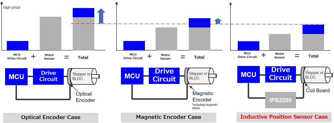
The last advantage is the low cost. In general, it’s easier to lower the total cost of inductive position sensors compared to optical or magnetic encoders, due to the number of elements and components used. The optical encoder sensor is inherently more expensive, while the magnetic encoder increased cost comes from the need for magnetic shielding, etc. Figure 4 compares the cost of the three position sensors.

To summarize, inductive position sensors can optimize position accuracy by designing the coil substrate to match the motor used and have high environmental resistance along with reduced weight of motor equipment. In addition, a motor control system with position sensing function can be realized at a lower cost compared to other position sensors. As a result, the use of this sensor is expanding in applications that require high-precision position detection in harsh environments, such as industrial motors, robots and medical equipment.
Finally, the product page for RA6T2, a 32-bit Arm® Cortex® MCU for motor control, includes a wealth of application notes and sample projects for motor control with encoder IF, sensorless control, BLDC motor control with inductive position sensor (introduced in the blog), and more. It can be applied to a wide variety of motor control devices.
Experience superior performance in motor control with the RA6T2 32-bit MCU and evaluation environment that allows for immediate evaluation.
Videos & Training
News & Additional Resources
| Title | Type | Date |
|---|---|---|
| Renesas’ New Resolver 4.0 Catalog Offers 80 Market-Ready Inductive Position Sensor Designs | News | Sep 15, 2022 |

