Understanding the principle and application of high efficiency motors: 2 of 3
BLDC motors have gained considerable attention for the ability to deliver high efficiency in a small package, and for their long service life and excellent controllability. In this session, we look at how we can control them to make effective use of their potential capabilities.
Connections are More Complicated
Figure 1 shows the appearance and inner structure of a typical type of BLDC motor—the inner rotor type. Note that this motor’s permanent magnet is attached to its rotor, and the coils are placed outside. This is quite different from a typical brushed DC motor, where the coils are on the rotor and the permanent magnet is outside. Since the BLDC motor’s rotor does not use coils, there is no need to supply it with current. That’s why there are no brushes.
But BLDC motors are more difficult to drive than brushed motors. With a brushed motor, all you need to do is to connect the power source to the positive and negative leads from the motor. The BLDC motor has a different from brushed dc motor to number of leads, and the connection is more complicated.
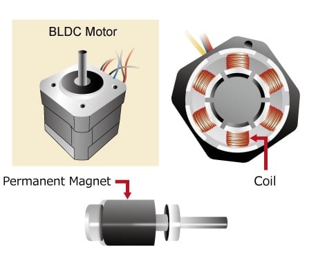
Figure 1: The Inside and Outside of a BLDC Motor.
The rotor is a permanent magnet, and does not pass current. Brushes and commutator are eliminated, allowing for longer service life.
Controlling the Magnetic Field
To rotate a BLDC motor, one needs to control the direction and timing of the current into the coils. Figure 2(a) illustrates a BLDC motor’s stator (coils) and rotor (permanent magnets). Let’s use this illustration to see how the rotor is made to turn. In this example we are using three coils, whereas in practice it is more common to use six or more. But here we look at just three coils, spaced at 120º. A motor, as we noted in our last session, performs the task of converting electrical energy into mechanical energy. So how does the motor in our illustration do this? Let’s look at what goes on inside.
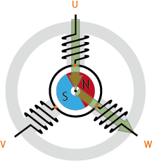
Figure 2(a): BLDC Motor’s Principle of Rotation.
Typical configuration: three coils with 120º spacing. Driven by controlling the phases and coil currents.
For our example, we show a 3-coil motor. Let’s label the coils U, V, and W. Remember that the passing of a current through a coil generates a magnetic field. Since there are three coils, there are three paths through which we can pass current; we can call these phase U (current into coil U), phase V (into coil V), and phase W. Let’s look first at phase U. If current moves through U only, magnetic flux is generated as shown by the arrow in Fig. 2(b). In actuality, all three coils are interconnected, through a single lead wire from each—and it is not possible to generate phase U in isolation. Figure 2(c) shows what happens when current moves through coils U and W (phase “UW”), with the arrows again showing the flux generated at each coil. The wide arrow in Figure 2(d) is the resultant flux—the result of the combined magnetic fields from U and W. This large flux will cause the inner rotor to turn until the S and N poles of the rotor permanent magnet are aligned on this arrow (with the N pole closest to the arrow tip).
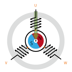
Figure 2(b): BLDC Motor Principle of Rotation.
Current flows through U and then W. The arrow shows flux generated by coil U.
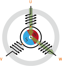
Figure 2(c): BLDC Motor Principle of Rotation.
Current flows through U and W. The two arrows show flux generated by coils U and W, respectively.
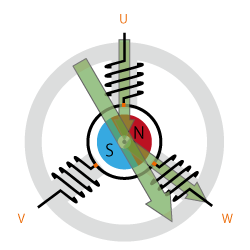
Figure 2(d): BLDC Motor Principle of Rotation.
The wide arrow shows the resultant flux—the sum of the flux produced by U and W.
Rotation is maintained by continually switching the flux so that the permanent magnet is constantly chasing the rotating magnetic field induced by the coils. In other words, energizing of U, V, and W must be continually switched so that the resultant flux keeps moving, producing a rotating field that continually pulls on the rotor magnet.
Figure 3 shows the relationship between energized phases and flux. As you can see, switching sequentially through modes 1 through 6 will cause the rotor to turn clockwise through one rotation. The speed of rotation can be controlled by controlling the rate at which the phases change. We use the name “120-degree conducting control” to the 6-mode control method described here.
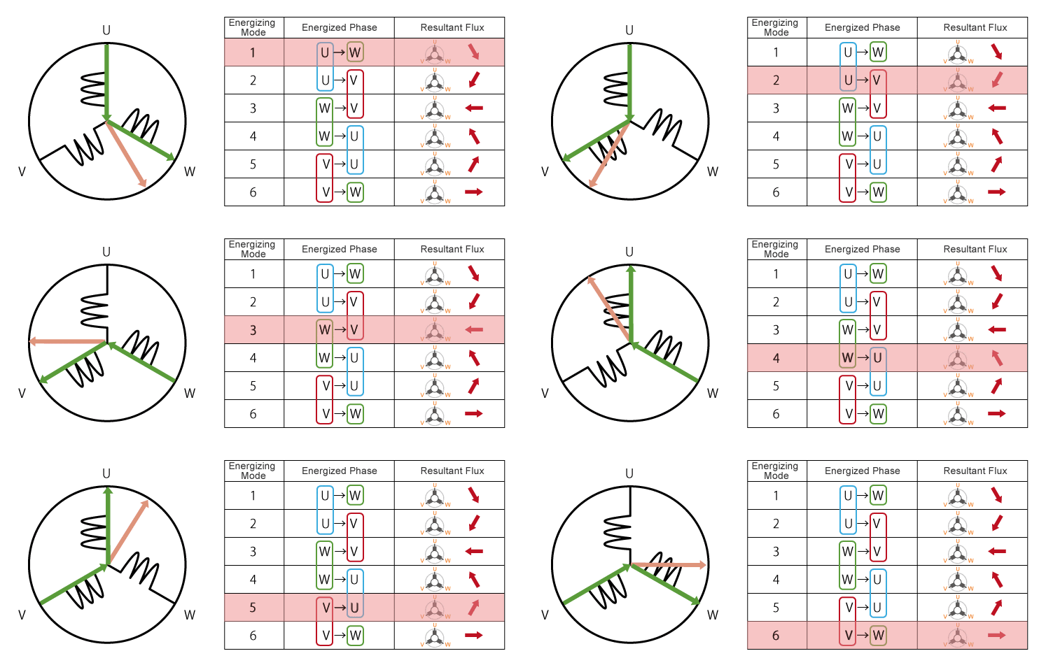
Figure 3: The changing resultant flux continually pulls the rotor magnet, causing the rotor to turn.
Sinusoidal Control Delivers Smooth Rotation
With 120-degree conducting control, there are only six resultant flux directions for driving the motor. For example, switching from Mode 1 to 2 (see Fig. 3) moves the resultant flux direction by 60º, pulling the rotor along accordingly. Switching from Mode 2 to 3 shifts the flux direction another 60º, again pulling the rotor. Repeating this process generates a continuous rotation, but it is a somewhat jerky rotation. In some cases, this jerkiness will create unwanted vibrations and mechanical noise.
As an alternative to 120-degree conducting control, we can use sinusoidal control to achieve smoother and quieter operation. With 120-degree conducting control, the motor is controlled by continually cycling through six fixed resultant fluxes. And as you can see in Figure 2(c), U and V both generate fluxes of equal magnitude. By more carefully controlling the current into U, V, and W, however, we can generate differing flux magnitudes at each coil, allowing us to more precisely vary the resultant flux. (See Fig. 4.)
By carefully adjusting the current flow into each of the three phases, then, we can achieve a more continuous change in resultant flux, resulting in smoother motor rotation.
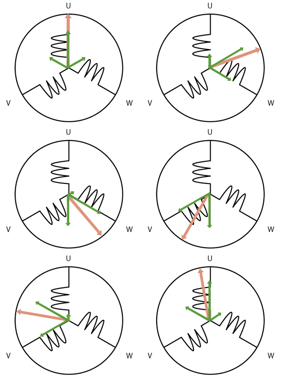
Figure 4: Sinusoidal Control.
By controlling the current into all three phases, resultant flux magnitude and direction can be controlled more precisely that with 120-degree conducting control, so as to achieve smoother rotation. Resultant flux is no longer limited to six discrete directions.
Control by Inverter
Let’s look again at the nature of the current into U, V, and W. For simplicity, let’s see how this works with 120-degree conducting control. Looking back to Figure 3, we see that in Mode 1 the current flows from U to W; in Mode 2, from U to V. As the arrows in the figure show, each change in the energized coil combination causes a corresponding change in the flux direction.
Now look at Mode 4. Here we have current moving from W to V; this is the just the reverse of Mode 1. With a brushed DC motor, this type of current reversal would be achieved using brushes and commutator. BLDC motors cannot by definition use brushes or other mechanical contact to achieve this reversal. Instead, they generally use inverter circuitry to implement this control.
And by using the inverter circuitry to also adjust the voltage into each coil, we can in addition control the magnitude of the current. A typical way to adjust the voltage is with pulse width modulation (PWM). In this approach, we alter the voltage by lengthening or reducing the pulse ON time (also referred to as the “duty cycle”: the ON time expressed as a ratio of the ON+OFF switching interval). Increasing the duty cycle has the same effect as raising the voltage; reducing the duty cycle has the same effect as lowering the current. (See Fig. 5.)
PWM can be implemented using MPUs equipped with dedicated PWM hardware. While 120-degree conducting control only requires two-phase voltage control and be implemented relatively easily in software, sinusoidal control uses three-phase voltage control and is considerably more complicated. Appropriate inverter circuitry is therefore essential for driving BLDC motors. Note that inverters can also be used with AC motors. But when a term such as “inverter type” is used with reference to consumer electronics, it is usually referring to a BLDC motor.
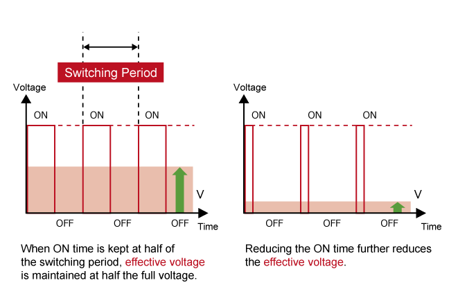
Figure 5: PWM Output vs. Output Voltage.
Varying the duty cycle (the ON time within each switching period) changes the effective voltage.
BLDC Motors and Positional Sensors
As we have seen, we drive BLDC motors by continually changing the directionality of the flux produced by the coils. The permanent magnets on the rotor continually chase the shifting rotating magnetic field, causing the rotor to turn.
So far, however, we have not looked at another important feature of these motors: their positional sensors. Because BLDC motor control must be coordinated with the rotor (magnet) position, these motors typically also include sensors to detect this position. Applying current when the rotor position is unknown may cause the rotor to turn in the wrong direction. The use of sensors prevents this problem.
Table 1 lists the typical types of sensors used in these motors. Different types sensors are used for different methods of control. Hall elements, with signal inputs spaced at 60º, are best for motors that use 120-degree conductingcontrol—where all that is necessary is to determine which phase to energize. More precise sensors—such as resolvers and optical encoders—are more appropriate with motors that use vector control (see below), where flux is more finely controlled.
While sensors offer obvious advantages, they come with disadvantages as well. Some sensors have low tolerance to dust, and require regular maintenance. Others operate properly over only a limited range of temperatures. The use of sensors, and the implementation of all the attendant circuitry, increases manufacturing costs; and highly precise sensors are of course the most expensive. “Sensorless BLDC motors” currently on the market eliminate the use of sensor entirely, as a way of reducing the costs of parts and maintenance. But this session, where we are explaining the principles of operation, we have assumes that sensors are being use to track the rotor position.
| Sensor Type | Typical Applications | Features |
|---|---|---|
| Hall Element | 120-deg. conducting control | Gets signal every 60 degrees. Relatively inexpensive. Poor tolerance to heat. |
| Optical Encoder | Sine-wave control, vector control | Two types: Incremental (detects displacement from origin) and absolute (detects current position). High resolution. Poor tolerance to dust. |
| Resolver | Sine-wave control, vector control | High resolution. Sturdy. Can be used in rough environments. |
Table 1: Positional Sensor Types and Features
Vector Control Maintains High Efficiency
As we have seen, sinusoidal control delivers smooth rotation by utilizing 3-phase current to smoothly control the flux. Where 120-degree conducting control energizes only two of the three (U, V, and W) phases at any one time, sinusoidal control is considerably more complicated—as it must accurately deliver differing amounts of current to all three phases.
One way of reducing this complication is with vector control, where calculations are used to convert the coordinate space, allowing 3-phase AC values to be handled as 2-phase DC values. This approach can only work, however, if high-resolution positional information is available for use in these calculations. One way of getting this information is through the use of high-precision sensors (optical encoders, resolvers, etc.). Another, “sensorless” way is estimate the position based on the magnitude of the current into each phase. In either case, the conversion of the coordinate space allows for direct control of torque-related electric current—allowing for highly efficient operation with little wasted current.
Implementation of vector control requires intensive mathematical processing, including the ability to rapidly solve the trigonometric functions needed to convert the coordinate space. The MCU used to control these motors will generally include an FPU (floating-point unit) and must be able to deliver considerable processing power.
In our next session, we will use the Renesas “Motor RSSK” development kit (actual kit name: “24V Motor Control Evaluation System for the RX23T”) to implement control of a working motor.
Module List
- What are Brushless DC Motors
- Controlling BLDC Motors
- Renesas Solutions for BLDC Motor Control