Overview
Let's play with a digital compass on GR-ADZUKI and examine the direction!
Preparation
Hardware
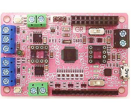
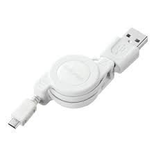
You will need a GR-ADZUKI board, a USB cable (Micro B type), and a digital compass using HMC5883L.
Connect the digital compass as shown here and set [Sketch] to the lower side of the slide switch of the GR-ADZUKI board.

Software
Since the digital compass can not be used in S4A, we will use the web compiler here. For the basic usage of the web compiler, please refer to the GR-ADZUKI Sketch Using a Web Compiler project.
You can also try IDE for GR. For basic usage of IDE for GR please refer to the GR-ADZUKI Sketch Using IDE for GR project.


Import Libraries for HMC5883L
We will use the Adafruit library. Download two zipped compressed libraries from the links below.
After creating the GR-ADZUKI project with the web compiler, upload from the project root. Upload as zip file.
You can also import libraries with IDE for GR, delete the file called "library.properties" before importing. If you do not delete it you will get a "Missing 'core-dependencies' from library" error.

Uploading two libraries will appear in the project tree as shown below.

Example
Open magsensor.ino located under examples in the Adafruit_HMC5883_Unified folder of the project tree and copy everything as follows.

Open gr_sketch.cpp as below and paste it under # include < Arduino.h >

After executing the build, write the adzuki_sketch.bin file to GR-ADZUKI and check the output with the serial monitor. The magnetic flux density (uT: Tesla) of X, Y, Z and the azimuth angle obtained from X and Y are displayed as follows.

In the example in the figure above it is 359.51, which means that X of HMC5883L faces almost north.

Sensor Output Timing
At the timing when the sensor output is ready, the HMC5883L generates a pulse on the DRDY signal as follows. Pulses of about 65ms interval can be confirmed. The azimuth angle is output when it is executed.

Using INT2 (Pin 25) of GR-ADZUKI, you can acquire the sensor value according to this pulse. The following is a sample program.
/*GR-ADZUKI Sketch Template Version: V2.01*/
#include <Arduino.h>
/***************************************************************************
  This is a library example for the HMC5883 magnetometer/compass

  Designed specifically to work with the Adafruit HMC5883 Breakout
  http://www.adafruit.com/products/1746

  *** You will also need to install the Adafruit_Sensor library! ***

  These displays use I2C to communicate, 2 pins are required to interface.

  Adafruit invests time and resources providing this open source code,
  please support Adafruit and open-source hardware by purchasing products
  from Adafruit!

  Written by Kevin Townsend for Adafruit Industries with some heading example from
  Love Electronics (loveelectronics.co.uk)

 This program is free software: you can redistribute it and/or modify
 it under the terms of the version 3 GNU General Public License as
 published by the Free Software Foundation.

 This program is distributed in the hope that it will be useful,
 but WITHOUT ANY WARRANTY; without even the implied warranty of
 MERCHANTABILITY or FITNESS FOR A PARTICULAR PURPOSE.  See the
 GNU General Public License for more details.

 You should have received a copy of the GNU General Public License
 along with this program.  If not, see <http://www.gnu.org/licenses/>.

 ***************************************************************************/

#include <Wire.h>
#include <Adafruit_Sensor.h>
#include <Adafruit_HMC5883_U.h>

/* Assign a unique ID to this sensor at the same time */
Adafruit_HMC5883_Unified mag = Adafruit_HMC5883_Unified(12345);
bool g_sensor_flag;

void displaySensorDetails(void)
{
  sensor_t sensor;
  mag.getSensor(&sensor);
  Serial.println("------------------------------------");
  Serial.print  ("Sensor:       "); Serial.println(sensor.name);
  Serial.print  ("Driver Ver:   "); Serial.println(sensor.version);
  Serial.print  ("Unique ID:    "); Serial.println(sensor.sensor_id);
  Serial.print  ("Max Value:    "); Serial.print(sensor.max_value); Serial.println(" uT");
  Serial.print  ("Min Value:    "); Serial.print(sensor.min_value); Serial.println(" uT");
  Serial.print  ("Resolution:   "); Serial.print(sensor.resolution); Serial.println(" uT");
  Serial.println("------------------------------------");
  Serial.println("");
  delay(500);
}

void sensor_rdy(){
  digitalWrite(10, HIGH);
  g_sensor_flag = true;
}

void setup(void)
{
  Serial.begin(9600);
  Serial.println("HMC5883 Magnetometer Test"); Serial.println("");

  pinMode(25, INPUT_PULLUP);
  attachInterrupt(2, sensor_rdy, FALLING);
  g_sensor_flag = false;

  /* Initialise the sensor */
  if(!mag.begin())
  {
    /* There was a problem detecting the HMC5883 ... check your connections */
    Serial.println("Ooops, no HMC5883 detected ... Check your wiring!");
    while(1);
  }

  /* Display some basic information on this sensor */
  displaySensorDetails();
}

void loop(void)
{
  /* Get a new sensor event */
  if(g_sensor_flag == true){
    sensors_event_t event;
    mag.getEvent(&event);

    float heading = atan2(event.magnetic.y, event.magnetic.x);
    if(heading < 0) heading += 2*PI;
    if(heading > 2*PI) heading -= 2*PI;
    float headingDegrees = heading * 180/M_PI;
    Serial.print("Heading (degrees): "); Serial.println(headingDegrees);
    g_sensor_flag = false;
  }
}