Overview
The GR-ADZUKI board was designed to make on-board connections easier, be it a DC motor, servo, sensor (distance, speed, magnetism, etc.), or battery box. GR-ADZUKI makes programming even more fun using S4A, a modified version of Scratch, which is an Arduino platform programming language geared for kids. You can also create Arduino-language sketches. With S4A firmware preinstalled at the factory, you can start programming your sketch as soon as you purchase it! (Windows users will need to install the USB driver from FTDI.)
The GR-ADZUKI board was originally planned to enhance engineering efficiency for the Robot Awareness Project. Robotic designs tend to involve rather fast and rough movements. Using breadboards in any kind of robot project can lead to disconnections and loose wiring, and eventually, malfunction. To resolve this issue, the board comes with terminal blocks that can be secured with screws. After having a bit of fun programming with Scratch, challenge yourself with a robot project using Arduino language!

GR-ADZUKI-FULL Key Features
- Built-in Renesas RL78/G13 Group 16-bit MCU
- Built-in terminal blocks for a DC motor, distance sensor and battery box
- Built-in pin headers and sockets for connecting a servo, accelerometer, digital compass, Micro SD module, voice jack, etc.
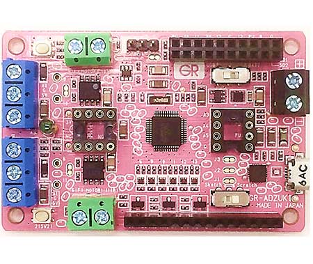
GR-ADZUKI Key Functions
LED
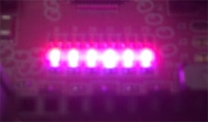
The GR-ADZUKI board comes with 6 LEDs, assigned to pins 6, 9, 10, 11, 12, and 13. The colors of the LEDs can also be changed: red is controlled by pin 22, green by pin 23, and blue by pin 24. For example, set pin 22 to HIGH to make the LEDs light up in red. Red and green can be mixed to create yellow light by setting pins 22 and 23 to HIGH. However, these color changes apply to all LEDS. If you want to make each LED a different color, you will need to apply dynamic lighting.
Light Sensor
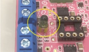
The phototransistor operates as a light sensor to measure brightness. The sensor is assigned to pin A2 and can be read with the Arduino analogRead function. Note that the value read with this command is not a lux measurement. Brightness values are as follows: 100 to 200 indicates a bright room, 500 to 600 indicates a cloudy sky, and 900 or above indicates a clear sky.
Button Switches (2)
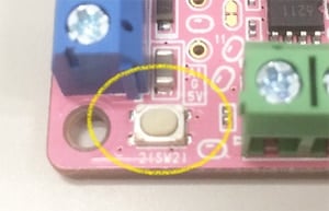
Two push button switches are included on the GR-ADZUKI board, assigned to pins 2 and 3, accordingly. The Arduino digitalRead function reads the value of the corresponding pin to determine whether the button is being pushed or not. Since there is no pull-up resistor, by executing pinMode (pin, INPUT_PULLUP) first, the function will read LOW when the switch is pushed, and HIGH when not. The switches can also act as external interrupts using attachInterrupt.
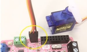
Servo Motor Pin Header
GR-ADZUKI includes a built-in pin header for connecting a servo motor (available at Akizuki Denshi). The pin header is assigned to pin 4 and can be controlled with the Arduino servo library. The XCL101 DC/DC converter generates the 5V supplied to the power supply VB pin. We recommend using a small servo motor as the supply current is only 100mA.
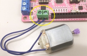
DC Motor Terminal Blocks (2)
The GR-ADZUKI board includes 2 built-in terminal blocks for connecting a DC motor. The wires can be easily attached using a Phillips (plus) screwdriver. The two blocks are assigned to pins 6/11 and pins 9/10, respectively. The motor can be controlled with the Arduino analogWrite function. The GR-ADZUKI board uses a BD6211F motor driver, which can supply up to 2A of current. However, when the board is connected to the PC via a USB connection, the motor can cause an overload to the PC. Even when using a small DC motor, make sure you specify 100 when setting the analogWrite function. The motor can be controlled to rotate forward or in reverse. When controlling with pins 6/11 (motor1) the motor rotates forward when pin 6 is HIGH and pin 11 is LOW, and rotates in reverse when pin 6 is LOW and pin 11 is HIGH. When both pins are LOW, the motor stops.
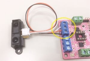
Distance Sensor Terminal Blocks
(2; for pressure and other sensors, as well as sensors that change resistance due to applied pressure)
GR-ADZUKI comes with two built-in terminal blocks for connecting a distance sensor. The wires can be easily attached using a Phillips (plus) screwdriver. The board was designed assuming the use of Sharp’s distance sensor (GP2Y0A21YK, available at Akizuki Denshi), but any 5V analog output sensor can be connected. Signal input for the two blocks is assigned to pins A0 and A1, respectively, and can be read with the Arduino analogRead function. The value increases as the object gets closer to the distance sensor; at approximately 10cm, the sensor will indicate 300 to 400, at 20cm, the value will be 100 to 200. Note that, if the object is too close to the sensor, reflected light from the infrared ray cannot be detected, and the value will start to diminish. In addition, partial pressure is input to the input signal from the 10kΩ resistor connected to GND and the 10kΩ resistor connected in series to input. As an example, you can also use these terminal blocks to connect a pressure sensor (available at Akizuki Denshi) to 5V and pin A0.
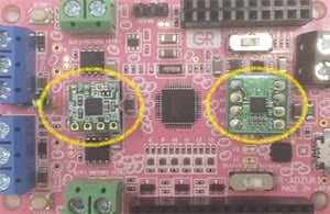
DIP Pin Sockets for Acceleration Sensor (Analog Output), Digital Compass (I2C Communication)
These built-in DIP sockets are for connecting the acceleration sensor (KXSC7-205) and the digital compass (HMC5883L). The acceleration sensor, or accelerometer, is assigned as follows: Pin A3 – X axis, pin A4 – y axis, and pin A5 – Z axis. The pins can be read with the Arduino analogRead function. The digital compass is assigned as follows: Pin 7 – SCL, pin 8 – SDA. The values of these pins can be read using the Arduino wire library.
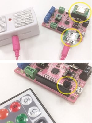
Expansion Pin Sockets for Micro SD, Audio Jack, and Infrared Remote Controller
Although it may look like pins have been assigned to the expansion pin socket randomly, the pins are actually lined up to allow connection of commercial products as is.
A Micro SD (available at Akizuki Denshi) module can be used with the Arduino SD library to easily create a data logger, while the WAV file player library makes it easy to play back sounds. Connecting an audio jack (available at Akizuki Denshi) allows you to output sound with adjusted volume using a speaker that includes an amplifier.
In addition, you can connect an infrared remote control receiving module (available at Akizuki Denshi) to control GR-ADZUKI operations remotely. For example, try remotely controlling the servo motor or playback functions.
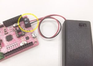
Terminal Block for Battery Box
The GR-ADZUKI board also comes equipped with a terminal block for connecting the battery box. The wires can be easily attached using a Phillips (plus) screwdriver. Input power supply is from 0.9V to 5V, so the board can run on 1 to 3 dry batteries (1.5V). When using this power supply input, make sure the switch is set to BATT.
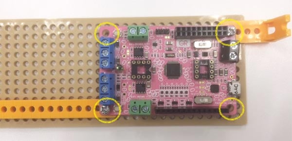
Screw Hole for Tamiya’s Universal Plate
The board has φ3mm screw holes on each of the four corners and is positioned on a 5mm grid for attachment to the Tamiya Universal Plate.
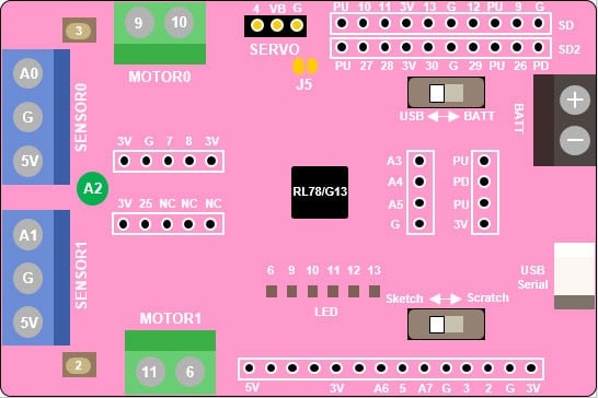
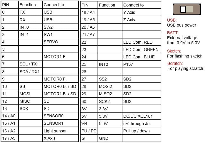
GR-ADZUKI Board Pin Map
Correction: The board and map card (included with the product) contains incorrect information concerning the MOTOR1 terminal block. Please make sure you confirm the wiring positions when connecting the motor. The correct information can be found on the Akizuki Denshi product site. (January 30, 2017)
Detailed Specifications
On-Board MCU
RL78/G13 (R5F100GJAF B 48-pin QFP)
ROM/RAM
256KB/20KB
Data Flash
8KB
Main Clock
32MHz (embedded in MCU)
Sub Clock
32.768kHz
Operating Voltage
2.7V to 5.5V*
* MCU can run on as low as 1.6V but the library spec indicates support from 2.7V.
Resources
Schematic/Design
- CR-5000/PWS Plot Output (PDF)
- GR-ADZUKI Schematic (PDF)
Sketch Reference
Create/Upload a Program
- GR-ADZUKI Special Projects
Project File for e2 studio
Project file for sketching in the Eclipse-based development environment e2 studio. For downloading and installing e2 studio, please refer to the e2 studio product page.
- Click to download. Import the archive file (zip) as an existing workspace from the menu 'File' -> 'Import' in e2 studio.
ADZUKI Sketch v204 Project File (ZIP)
Note: This is a project exported in e2 studio version 7.2.
Technical Support
- Gadget Renesas Users' Forum
This online support community introduces various gadgets, programs and new product information. Feel free to post your own gadgets or ask questions. - E-mail: [email protected]
Related Websites