Overview
Description
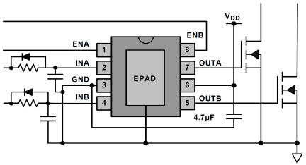
The ISL89163, ISL89164, and ISL89165 are high-speed, 6A, dual channel MOSFET drivers with enable inputs. Precision thresholds on all logic inputs allow the use of external RC circuits to generate accurate and stable time delays on both the main channel inputs, INA and INB, and the enable inputs, ENA and ENB. The precision delays capable of these precise logic thresholds makes these parts very useful for dead-time control and synchronous rectifiers. Note that the enable and input logic inputs can be interchanged for alternate logic implementations. Three input logic thresholds are available: 3. 3V (CMOS), 5. 0V (CMOS or TTL compatible), and CMOS thresholds that are proportional to VDD. At high switching frequencies, these MOSFET drivers use very little internal bias currents. Separate, non-overlapping drive circuits are used to drive each CMOS output FET to prevent shoot-through currents in the output stage. The start-up sequence is designed to prevent unexpected glitches when VDD is being turned on or turned off. When VDD ~1V, an internal 10kΩ resistor between the output and ground helps to keep the output voltage low. When ~1V VDD UV, both outputs are driven low with very low resistance and the logic inputs are ignored. This insures that the driven FETs are off. When VDD > UVLO, and after a short delay, the outputs now respond to the logic inputs.
Features
- Dual output, 6A peak currents, can be paralleled
- Dual AND-ed input logic, (input and enable)
- Typical ON-resistance <1Ω
- Specified Miller plateau drive currents
- Very low thermal impedance (θJC = 3°C/W)
- Hysteretic Input logic levels for 3.3V CMOS, 5V CMOS, TTL, and Logic levels proportional to VDD
- Precision threshold inputs for time delays with external RC components
- 20ns rise and fall time driving a 10nF load.
Comparison
Applications
- Synchronous Rectifier (SR) Driver
- Switch mode power supplies
- Motor Drives, Class D amplifiers, UPS, Inverters
- Pulse Transformer driver
- Clock/Line driver
Documentation
|
|
|
|
|---|---|---|
| Type | Title | Date |
| Datasheet | PDF 458 KB | |
| Brochure | PDF 12.71 MB 日本語 | |
| End Of Life Notice | PDF 603 KB | |
| Product Change Notice | PDF 326 KB | |
| Product Change Notice | PDF 84 KB | |
| Product Advisory | PDF 143 KB | |
| Application Note | PDF 509 KB | |
| Application Note | PDF 397 KB | |
| Application Note | PDF 576 KB | |
9 items
|
||
Design & Development
Models
ECAD Models
Schematic symbols, PCB footprints, and 3D CAD models from SamacSys can be found by clicking on products in the Product Options table. If a symbol or model isn't available, it can be requested directly from the website.


