Overview
This project introduces attaching an infrared module to the GR-COTTON board as a remote control receiver.
Preparation
This project requires a GR-COTTON board, a USB cable (Micro B type), and an infrared receiver.
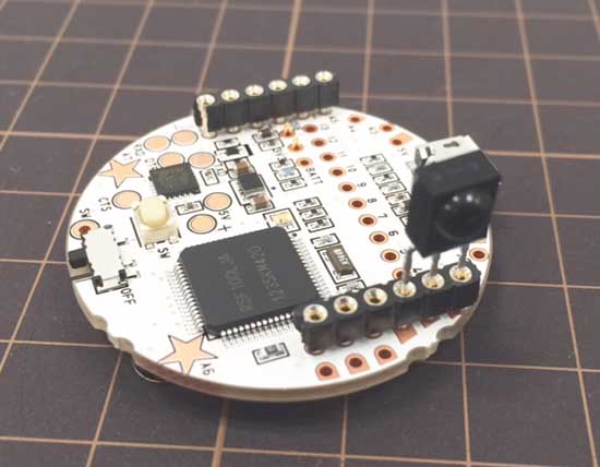
You will need to install a pin socket (round pin) on GR-COTTON. Cut the legs of the infrared module to a suitable length. As the infrared module’s legs are thin, they don’t properly fit in the sockets used for the humidity/temperature sensor or digital compass. Solve the problem by doubling up with a round pin-type socket.
The infrared receiver can be purchased from SparkFun Electronics and the pin socket (round type) can be purchased from the Akizuki Denshi website.
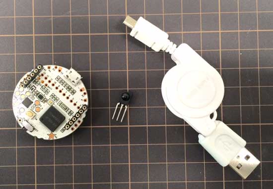
Connect the infrared module to GR-COTTON as shown in the photo to the right.
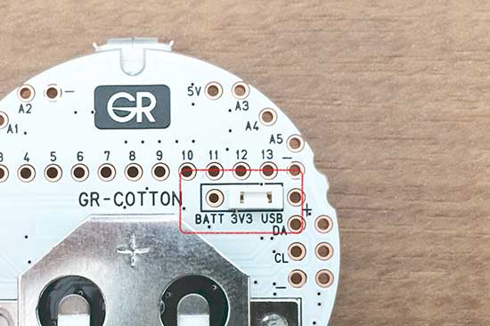
Make sure the white jumper on the reverse side of GR-COTTON is moved to the “3V3 USB” side. If it is set to the BATT side, remove and reinsert it into the USB side.
Confirming Infrared Reception
First, confirm that the infrared module is catching the infrared rays from the remote control.
This sample simply programs the blue LED to echo the infrared rays.
#include <arduino.h>
void setup() {
  pinMode(2, INPUT_PULLUP);
  pinMode(24, OUTPUT); //blue led
  digitalWrite(24, HIGH);
}

void loop() {
  digitalWrite(24, digitalRead(2));
}
Conserving Power During Intervals of No Infrared Ray Reception
It is best to conserve power during periods when the remote control is not in operation.
This sample programs power conservation during intervals between reception of infrared rays. It resembles a button switch program, using an interrupt assigned to pin 2.
#include <arduino.h>

void ir_receive(){
  digitalWrite(23, LOW);
  setPowerManagementMode(PM_NORMAL_MODE); // for use delay
  delayMicroseconds(1000);
  digitalWrite(23, HIGH);
}
void setup() {
  pinMode(2, INPUT_PULLUP);
  attachInterrupt(0, ir_receive, FALLING);

  pinMode(23, OUTPUT); //green led
  digitalWrite(23, HIGH);
}

void loop() {
  setPowerManagementMode(PM_STOP_MODE);
  delay(0xffffffff); // into stop mode
}
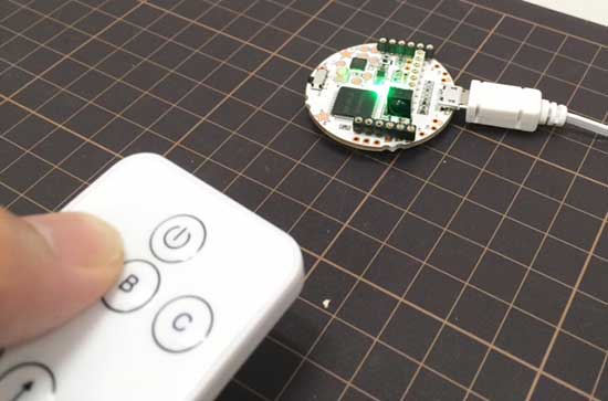
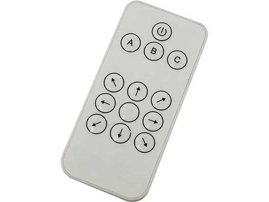
Pressing buttons A, B or C activates LEDs in this sample, as shown to the right.
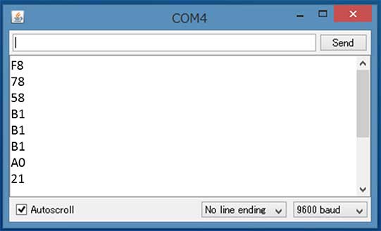
This remote control adheres to the NEC format. The sample program analyzes the NEC format-compliant signal and turns on the LED as well as displays the signal content in the serial monitor.
#include <arduino.h>

#define IR_PIN 2
#define IR_INTERRUPT 0

uint8_t g_ir_data = 0;
bool    g_ir_available = false;

void ir_receive_interrupt();
void ir_receive_start();
uint8_t ir_getData();
bool ir_available();

void setup() {
  setPowerManagementMode(PM_STOP_MODE);
  Serial.begin(9600);
  pinMode(IR_PIN, INPUT_PULLUP);
  ir_receive_start();

  pinMode(22, OUTPUT);
  pinMode(23, OUTPUT);
  pinMode(24, OUTPUT);
  digitalWrite(22, HIGH);
  digitalWrite(23, HIGH);
  digitalWrite(24, HIGH);

}

void loop() {
  ir_receive_start();
  delay(0xFFFFFFFF); // hold STOP mode until receiving IR signal.

  if(ir_available()){
    Serial.println(ir_getData(), HEX);
    Serial.flush();
    switch (ir_getData()) {
      case 0xD8: // POWER BUTTON
        digitalWrite(22, LOW);
        delay(100);
        digitalWrite(22, HIGH);
        break;
      case 0xF8: // A BUTTON
        digitalWrite(23, LOW);
        delay(100);
        digitalWrite(23, HIGH);
        break;
      case 0x78: // B BUTTON
        digitalWrite(24, LOW);
        delay(100);
        digitalWrite(24, HIGH);
        break;
      case 0x58: // C BUTTON
        digitalWrite(22, LOW);
        digitalWrite(24, LOW);
        delay(100);
        digitalWrite(22, HIGH);
        digitalWrite(24, HIGH);
        break;
      default:
        break;
      }
    }
}

/************ IR utility function ***************/
void ir_receive_interrupt(){

  unsigned long last_time;

  detachInterrupt(IR_INTERRUPT);
  last_time = micros();

  // confirm if reader code is correct
  uint8_t err = 0;
  while(!digitalRead(IR_PIN)){ // until change from low to high
    if((micros() - last_time) > 10000){ // interval low should be 9ms or less
        err = true;
        break;
    }
  }
  while(digitalRead(IR_PIN)){ // until change from high to low
    if((micros() - last_time) > 15000){ // interval of reader code should be 13.5ms or less
        err = true;
        break;
    }
  }
  if(((micros() - last_time) < 13000) || (err == true)){ // Unknown code
    attachInterrupt(0, ir_receive_interrupt, FALLING);
    g_ir_available = false;
    return; // not available remote controller
  }

  // get data
  uint8_t receive_count = 0;
  uint8_t temp_ir_data[4] = {0};
  g_ir_data = 0;
  last_time = micros();
  while((32 > receive_count) && ((micros() - last_time) < 80000)){
     // interval of a frame data should be 76.5ms or less
    last_time = micros();
    while(!digitalRead(IR_PIN) && ((micros() - last_time) < 1000)){
     // interval of low state is about 0.56ms.
    }
    while(digitalRead(IR_PIN) && ((micros() - last_time) < 2500)){
     // interval of a bit is between 1.125ms and 2.25ms
    }
    if((micros() - last_time) > 1500){
        bitSet(temp_ir_data[receive_count / 8], receive_count % 8);
    }
    receive_count++;
  }

  if(temp_ir_data[2] == (uint8_t)~temp_ir_data[3]){
        g_ir_data = temp_ir_data[2]; // set actual data
        g_ir_available = true;
  }

}

void ir_receive_start(){
  attachInterrupt(IR_INTERRUPT, ir_receive_interrupt, FALLING);
}

uint8_t ir_getData(){
  g_ir_available = false;
  return g_ir_data;
}

bool ir_available(){
  return g_ir_available;
}