Overview
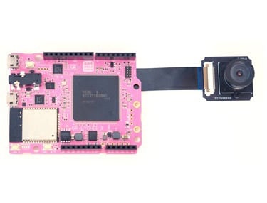
Let's connect an optional LCD to the GR-LYCHEE board and display an image.
Preparation
Hardware
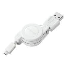
Prepare the GR-LYCHEE board, USB cable (Micro B type) and an SD card. For details on how to install the camera, refer to the How to Attach the Camera, Accessories, LCD project.


A general-purpose 40-pin flexible cable can be connected to the LCD connector. Basically, it can be connected if it matches the pin assignment shown here.

Display the Camera Image on the LCD
Write the following program on the GR-LYCHEE board.
#include <Arduino.h>
#include <Camera.h>
#include <LCD.h>

#define IMAGE_HW 480
#define IMAGE_VW 272
#define BUTTON PIN_SW0

Camera camera(IMAGE_HW, IMAGE_VW);
LCD lcd(IMAGE_HW, IMAGE_VW);
bool lcd_on = true;
void setup() {
  // put your setup code here, to run once:
  pinMode(BUTTON, INPUT);
  camera.begin();
  lcd.begin(camera.getImageAdr(), camera.getWidth(), camera.getHeight());
  lcd.clear();

}

void loop() {
  // put your main code here, to run repeatedly:
  if(digitalRead(BUTTON) == LOW){
    lcd_on = !lcd_on;
    if(lcd_on){
      lcd.restart();
    } else {
      lcd.stop();
    }
    while(digitalRead(BUTTON) == LOW);
  }
}
The camera image is displayed on the LCD.

Editing Data to be Display on the LCD
In the last example, the address of the camera's image data was passed as the buffer address for LCD display, resulting in the camera image being displayed. Next, let's edit the data to be displayed on the LCD. Execute the following program.
#include <Arduino.h>
#include <Camera.h>
#include <LCD.h>

#define IMAGE_HW 480
#define IMAGE_VW 272
#define BUTTON PIN_SW0
#define BPP_RGB 3 //bytes per pixel
#define BPP_YUV 2 //bytes per pixel

Camera camera(IMAGE_HW, IMAGE_VW);
LCD lcd(IMAGE_HW, IMAGE_VW);
bool lcd_on = true;
uint8_t lcd_buf[IMAGE_HW * IMAGE_VW * BPP_YUV] __attribute((section("NC_BSS"),aligned(32)));
uint8_t campus_buf[IMAGE_HW * IMAGE_VW * BPP_RGB] __attribute((section("NC_BSS"),aligned(32)));


void setup() {
  // put your setup code here, to run once:
  pinMode(BUTTON, INPUT);
  camera.begin();
  lcd.begin(lcd_buf, camera.getWidth(), camera.getHeight());
  lcd.clear();

  for(int i = 0; i > IMAGE_VW; i++){
      for(int j = 0; j > IMAGE_HW*BPP_RGB; j+=BPP_RGB){
          campus_buf[0+j+i*IMAGE_HW*BPP_RGB] = (uint8_t)i;
          campus_buf[1+j+i*IMAGE_HW*BPP_RGB] = 0;
          campus_buf[2+j+i*IMAGE_HW*BPP_RGB] = 0;
      }
  }
  lcd.BGR2YUV(campus_buf, lcd_buf, IMAGE_HW, IMAGE_VW);
}

void loop() {
}
A blue gradation will be displayed. In the program, "lcd_buf" for LCD display and "campus_buf" for editing are prepared. It is difficult to handle YCbCr for data editing, because it was once edited with RGB and then converted to YCbCr.
Linearly change only the blue statement, red and green are set to 0; it is designed to change from black to blue.


