IO-Link Sensors

Overview

Description

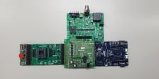
IO-Link is a worldwide open standard protocol used for communication between devices in industrial settings. It facilitates bi-directional data exchange between a master device, actuators, and sensors. This system supports various IO-Link slave sensors, including those for pressure, temperature, humidity, and electrical power measurement. Rapid prototyping is possible using Pmod™ boards and sample code.

System Benefits​:

  • Pmod evaluation boards and software are available for rapid prototyping.
  • IO-Link PHY chips integrate LDO, reducing BOM count.
  • Multiple PHY and MCU options scale cost and performance according to application requirements.

Comparison

Applications

  • IO-Link devices​
  • Pressure sensors​
  • Temperature and humidity sensors​
  • Low voltage power measurement​
  • Load cells​
  • Inductive sensors​
  • Industrial sensors

Winning Combinations Interactive Diagram

Select a block to discover products for your design

Template 2 Connector Line.236 JP174 JP174 JP174 Connector double arrow.185 Connector Line Connector Line.190 Connected signals arrow Connector Line.196 Connector Line.197 Sheet.30 Connector Line Connector Line.160 Connector Line.161 Connector Line.227 Connector Line.229 Connector Line.234 Connector Line.235 Connector Line.57 3.3V 3.3V 3.3V Pressure Sensor Pressure Sensor Pressure Sensor 3.3V 3.3V 3.3V L+ (24V) L+ (24V) L+ (24V) CQ CQ CQ L- (0V) L- (0V) L- (0V) L+ (24V) L+ (24V) L+ (24V) CQ CQ CQ L- (0V) L- (0V) L- (0V) IO-Link Device Board No. 1 IO-Link Device Board No. 1 IO-Link Device Board No. 1 IO-Link Device Board No. 2 IO-Link Device Board No. 2 IO-Link Device Board No. 2 Sheet.71 Sheet.73 Sheet.74 Sensor Signal Conditioner Sensor Signal Conditioner 1 Sensor Signal Conditioner Sensor Signal Conditioner IO-Link PHY IO-Link PHY 1 IO-Link PHY IO-Link PHY Buck Buck Buck Sensor Signal Conditioner.266 Temperature & Humidity Sensor Temperature & Humidity Sensor Temperature & Humidity Sensor I2C I2C I2C MCU.267 MCU 2 MCU MCU I2C I2C I2C UART UART UART IO-Link PHY.269 IO-Link PHY 2 IO-Link PHY IO-Link PHY LDO LDO LDO UART UART UART IO-Link Master Board IO-Link Master Board IO-Link Master Board IO-Link Master Board IO-Link Master PHY IO-Link Master PHY IO-Link Master PHY MCU MCU MCU Sheet.101 Sheet.102 Connector Line Connector Line.160 Connector Line.161 Connector double arrow.123 Connector Line.124 Connected signals arrow.125 Connector Line.126 5V 5V 5V Pressure Sensor Pressure Sensor Pressure Sensor IO-Link Device Board No. 3 IO-Link Device Board No. 3 IO-Link Device Board No. 3 Sheet.130 Sheet.131 Sensor Signal Conditioner.132 Sensor Signal Conditioner 3 Sensor Signal Conditioner Sensor Signal Conditioner I2C I2C I2C MCU.135 MCU 3 MCU MCU I2C I2C I2C UART UART UART IO-Link PHY.139 IO-Link PHY 3 IO-Link PHY IO-Link PHY LDO LDO LDO UART UART UART Sheet.143 Connector double arrow.164 Connector Line.165 Connected signals arrow.166 20mA 5Vmax.168 5V 5V Shunt.169 Shunt Shunt IO-Link Device Board No. 4 IO-Link Device Board No. 4 IO-Link Device Board No. 4 Sheet.172 Sensor Signal Conditioner.173 Precision Digital Power Monitor Precision Digital Power Monitor Precision Digital Power Monitor I2C I2C I2C MCU.176 MCU 4 MCU MCU I2C I2C I2C UART UART UART IO-Link PHY.180 IO-Link PHY 4 IO-Link PHY IO-Link PHY LDO LDO LDO UART UART UART Circle UART UART UART UART UART UART Circle.201 Connector Line.202 Connector Line.203 Connector Line.204 L+ (24V) L+ (24V) L+ (24V) CQ CQ CQ L- (0V) L- (0V) L- (0V) Connector Line.208 Connector Line.209 Connector Line.210 L+ (24V) L+ (24V) L+ (24V) CQ CQ CQ L- (0V) L- (0V) L- (0V) Shunt Sheet.223 Sheet.224 Sheet.225 Connector Line.160 Connector Line.161 VINP VINP VINP VINM VINM VINM VBUS VBUS VBUS Connector Arrow To Load To Load To Load Connector Arrow.245 VIN = 0 to 60V VIN = 0 to 60V VIN = 0 to 60V JP174.247 JP174 JP174
Exiting Interactive Block Diagram

Videos & Training