DIY: Do-it-yourself. It’s a popular topic for television shows, commercials, magazines, and blogs. But DIY isn’t always the best choice, and sometimes a job is best left to the professionals.
Designers who need to integrate sensing elements into their system face this dilemma when it comes to sensor signal conditioning — Do I buy a specially designed Sensor Signal Conditioner (SSC) or design my own using a standard microcontroller with integrated mixed-signal capabilities? There are an increasing number of MCU’s with integrated amplifiers, ADCs, and DACs. And most systems that interface with sensors already have some type of an MCU or DSP for handling other tasks, so it seems to make sense to use something that is already available.
As with most DIY projects, however, there are many unforeseen complexities, details, and pitfalls involved in the interface, linearization, and temperature compensation necessary to produce consistently accurate results from a sensor element. Because I hear this question frequently from sensor system designers, I thought it would be helpful to explore some of these issues to help them make the right choice when it comes to their specific application.
It is critical to understand that sensing transducers are like individuals — no two are alike. No matter how well the manufacturers design and produce them, they will all have unique characteristics. Even though datasheets for transducers will give tolerances and ranges for span, sensitivity, and temperature dependence, these are rarely consistent enough to provide the accuracy required for most systems. This means that in almost all cases, some type of calibration must be performed for each and every sensing element. If not done efficiently, the time and resources consumed for calibration can easily eclipse any savings that might result from a do-it-yourself approach using generic microcontrollers, and this is often overlooked when making the tradeoff merely from a bill of materials point of view.
Calibration, then, is a key consideration in the decision process of buying versus designing a sensor interface. If the sensing elements are highly linear and relatively insensitive to temperature variations, calibration might be as simple as measuring at two points of the measured quantity (pressure, humidity, angle, etc.) at a single temperature and calculating a slope and offset. For the vast majority of sensors, however, the situation is much more complex.
It is not uncommon for the response across the input range to be a polynomial of third order or higher, and temperature dependence can often be of second order or higher. Calibration requires measuring n+1 points across each variable, where n is the order of polynomial response, and using those points to calculate an inverse multivariate curve fit. While state-of-the-art microcontrollers might have the computing horsepower to make these calculations, the time and effort involved in designing and testing custom software to efficiently implement such a curve fit that will converge with high accuracy across a wide range of conditions are far from trivial.
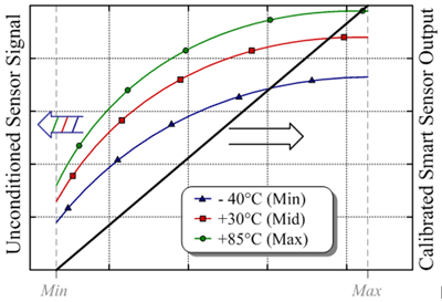
The figure below shows an example of how raw data from a sensor (left axis) is mapped to a linearized, temperature-compensated output (right axis).

Additionally, the process of collecting the calibration data itself can be quite costly, especially over temperature, so it is critical to design the system with the minimum number of measurement points necessary to meet system accuracy requirements.
Standard products or custom ASICs from Renesas that are specifically designed for sensor signal conditioning take these considerations into account and have numerous advantages over the DIY approach, including:
- Proprietary DSP engines and algorithms targeted to maximize the efficiency of implementing polynomial curve fitting.
- Correction factors are applied fully in the digital domain so that linearization and temperature compensation are precise and consistent. Further, the corrections are independent with respect to input and temperature so that fitting in one domain does not affect the other. This eliminates any need to repeat calibration versus pressure after temperature correction is applied or vice-versa, which can increase the time and cost dramatically.
- Custom software, developed with decades of real world sensor conditioning experience, performs the curve fitting calculations and returns a set of coefficients that are tailored to the application and SSC. This software is supplied as a .DLL file that can be integrated easily into the final production and test system.
- Design support in the form of evaluation kits, graphical software interfaces that assist optimization of the calibration sequence, and application engineers with many years of design, production, and troubleshooting experience.
While calibration is the key consideration for designing a cost-effective, accurate sensing system, there are other issues that are important as well. These include digital resolution and signal to noise ratio of the signal chain, biasing the sense element accurately, immunity to noise and power supply variation, ESD and EMI/EMC performance, elevated temperature and voltage operation, sensor diagnostics, safety-critical performance and analysis, and size and power constraints.
Doing it yourself can be challenging and satisfying, especially for engineers, but sometimes things are best left to the experts. If you have a sensor-based design and would like to consult with an expert, please visit renesas.com/ssc for more detailed information and an opportunity to request information or support by using the Tools and Support links at the top of the page.
You can view the entire Renesas SSC portfolio including technical documentation and evaluation tools at renesas.com/ssc.
