This blog follows on from my first blog looking at some of the more unique peripheral available on the RA microcontroller family, in the last blog we looked at the Data Operating Circuit (DOC), a unique peripheral that provides a simple processing element that can be used to make basic decisions without CPU intervention.
In this blog we’ll look at the Data Transfer Controller (DTC) , a peripheral that has been designed to provide a simple, but extremely flexible mechanism to transfer data between a peripheral and memory or memory and a peripheral. In the next blog we will see how we can combine the DOC and the DTC to create a complete intelligent subsystem that can operate without any CPU intervention. A Data Transfer Controller can be found on all the members of the RA microcontroller family.
The DTC use a simple programmable controller to make data transfers between memory and peripherals, and vice versa, rather than using a large, dedicated hardware block for this task, such as is used by the Direct Memory Access Controller (DMAC). This programmability provides us with a much higher level of flexibility in its operation compared to using a DMAC.
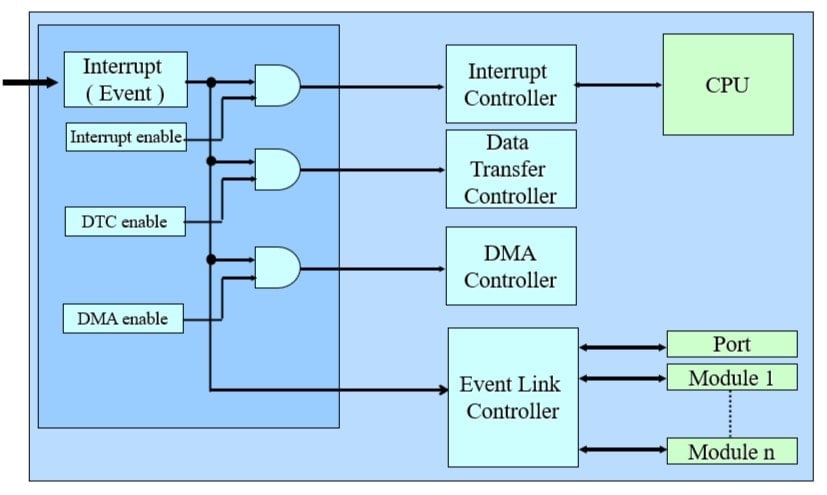
On the RA family, an event (or interrupt) , triggered by the CPU, by a peripheral on the device, or by an external pin can all generate a number of actions on the device. You can see a simplified diagram of the interrupt controller below, here you can see an event can trigger a number of actions, a traditional interrupt, that changes the direction of the application, a DMAC transfer, or a DTC transfer, it’s also possible to trigger more than one of these from a single event. You can also see an additional type of action can be created, using our Event Link controller, which allows us to directly connect peripherals together, which we will discuss in a future blog.

So, let’s look at the DTC in detail.
The main advantage of this programmability is that it holds all the required set-up information for the transfer not in a fixed set of on chip registers like in a DMA controller, but in a small block of on chip SRAM. This means that the DTC controller can be used not just to create one or two channels of data transfer, but 10 or 20 or even more if required if required. The only requirement is that for each channel that you define, you require a small block of SRAM dedicated to holding that specific channel configuration information. The main disadvantage of this mechanism is that for each transfer a few cycles must be taken to read the configuration data held in the SRAM before each transfer takes place, so generally the DTC transfer is slower than a DMA transfer.
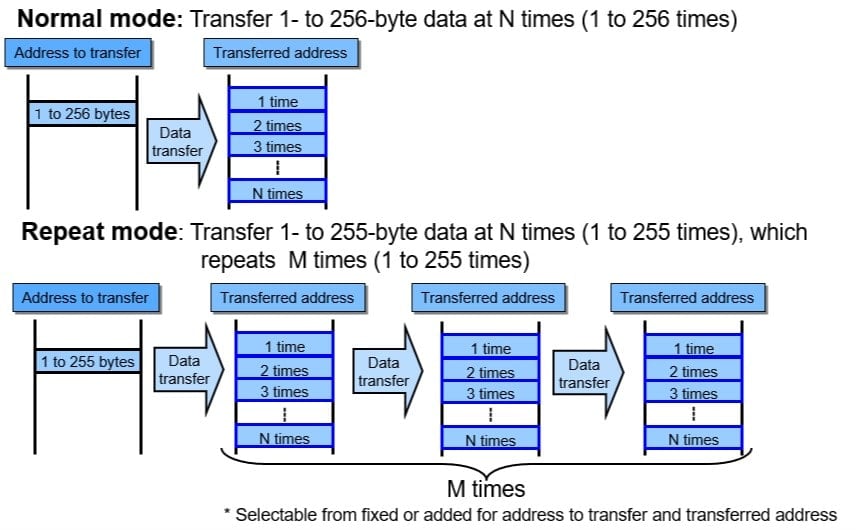
The DTC can transfer 1 byte or more than one byte, between a peripheral and memory or memory and peripheral up to 256 times. The source and destination address for the transfer each can be the same address, or it can be incremented or decremented independently, so creating a buffer structure in memory.
At the end of the transfer, the DTC can generate an interrupt, to tell the CPU the data is ready, or it can trigger a second DTC transfer. This can be used to chain several transfers together, and is what we call, funnily enough, chain mode. This chain mode can be especially useful if the movement of multiple pieces of data between peripherals and memory is required. Chain mode is particularly interesting when used with the DOC we discussed previously, as this means that multiple transfers from various locations in memory and or peripheral can be triggered by one interrupt source. For instance, this means that with one interrupt, such as the ADC interrupt, we can cause comparison data to be loaded into the DOC, and by chaining a second transfer, we can load the DOC with the data from the ADC to be compared, all completely automatically, with any CPU involvement. This ability for one interrupt to generate a complex sequence of different transfers is extremely powerful, not only when used with the DOC. Some of the different operating modes of the DTC are shown in the figure below.

The DTC can also be placed into repeat mode, where it will repeat the transfer an additional number of times. For most applications the flexibility of the DTC provides a perfect comprise, between speed, flexibility and of course device cost. You can create automated transfers between any peripheral and memory almost without limit.
The Data Transfer Controller provides an ideal method for automating the transfer of data between peripherals and memory, without any CPU intervention. The use of the DTC in chain mode when transferring data to the DOC, provides us with the ability to make simple tests on many pieces of data without any CPU intervention, so providing the chip itself with the ability to make simple decisions.
Hopefully you can see how the DTC can be much more flexible than the traditional DMAC, if you need the highest data transfer speeds, the DMSAC is still the most appropriate method and almost all the RA microcontrollers include a number of DMAC channels, but for flexibility, and the way you can manage data the DTC wins hands down for flexibility, and you can create many channels, only limited by the available SRAM on the device.
In the next blog we’ll look at how you can combine the DTC and DOC with the ADC to create an intelligent analogue sampling system that can operate entirely without any CPU intervention, so potentially reducing the demand on the CPU and even saving power consumption by turning off the CPU while the system runs.
