In this blog, we'll look at another one of the more unusual and less understood peripherals available in the RA microcontroller family.
In previous blogs, we looked at two of the peripherals that allow you to create complete autonomous subsystems on a typical RA microcontroller, reducing the CPU demand in your system by automating basic low-level tasks and often saving power consumption, being able to put the CPU to sleep while low-level systems tasks are managed automatically by the hardware. In the past blogs, we looked at the Data Operating Circuit, the Data Transfer Controller and how we could combine these to automate simple I/O tasks that can operate without CPU intervention, and wake up the CPU when an important event occurs.
In this blog, we'll look at the Event Link Controller (ELC), a peripheral which allows us to directly link peripherals in hardware on RA microcontrollers, so an event such as a timer timing out or an I/O port changing state can be used to trigger the start of an ADC conversion cycle, trigger a timer to start counting or to capture the time of the event. This is all done with a predictable latency, based on the relevant peripheral clocks, so a device can respond to an external event much quicker than using the CPI's interrupt system, and it can also reduce the complexity of the systems software as some events can be handled in hardware rather than relying on an interrupt to be serviced. This can be especially useful in systems with a high interrupt load, where background tasks can almost be completely offloaded from the CPU.
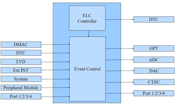
So let's look in a little more detail at how this works. The diagram below shows a greatly simplified diagram of the Event Link Controller. You can see that almost every peripheral on the chip (most of which can be used to generate an interrupt or a DMAC or DTC transfer) can be used to trigger an event inside the Event Link Controller. Each of these events can then be used to trigger an action in a number of the peripherals or to change the state of an I/O pin.
For instance, a timer timing out or an input capture event can be connected to the Analog-to-Digital Converter (ADC) and can start an ADC conversion cycle. The arrival of a message on a serial interface could cause a pin to change state. These events can even be chained together to create more complex interactions directly between the peripherals. This can allow you to automate many low-level events, and by combining some of the peripherals we have already discussed with the ELC, we can create quite complex subsystems, which all can operate without CPU intervention. Each connection in the ELC will occur within 1 – 2 clock cycles of the receiving peripherals clock and does not rely on the CPU to react, so we aren't reliant on the interrupt latency of your application to respond to asynchronous events.
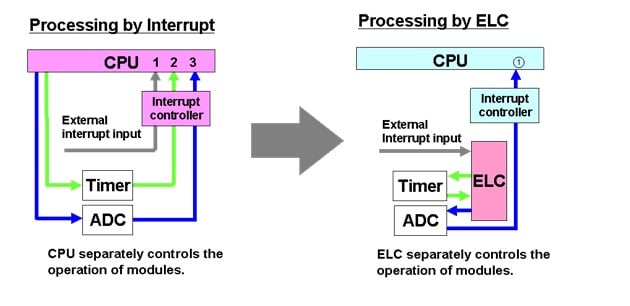
A simple example of using the Event Link Controller is shown below. An external interrupt causes a timer to start after the timer overflows, this then causes the ADC to start conversion. When this system is implemented using interrupts on a traditional microcontroller, three interrupts are required. One for the external interrupt, one for the timer overflow interrupt and one for the ADC end of conversion, with the resulting CPU overhead and, of course, the software required for each Interrupt Service Routine.
The system will also experience some jitter, especially if the system has many other, often higher priority, interrupts active, or is using an operating system, which may be handling higher priority tasks when one or more of these interrupts occur.

The Event Link Controller can handle the whole function. After the Event Link Controller is initialized, the whole process can be handled automatically without any CPU involvement until the complete process is finished. We can compare the process flow of using the Event Link Controller against the use of interrupts in the next diagram.
In a typical microcontroller application, after each interrupt is generated, we must service each interrupt. This results in a delay and, depending on the software, some jitter. In a microcontroller with the Event Link Controller, each event triggers the next peripheral automatically. The CPU is only interrupted after the ADC conversion has finished.
So in this example, we have almost no jitter, as each peripheral starts 1 – 2 clock cycles after the generating event, and is not affected at all by the condition of the CPU, whether it's handling a priority task or not. We also have additional savings, apart from the initialization, there is no software required for this process, so the code space required for the application can be reduced.
We could also go even further to automate this example and reduce CPU load, by using the DTC. We could automatically transfer the data from the ADC into a buffer in SRAM. Therefore, we could choose to interrupt the CPU perhaps only after every 100 or 200 readings. If we also include some other intelligent functions, such as the Data Operating Circuit, or we decide to use the ADC comparison function, we can go even further, and only interrupt the CPU when a preset analog value is exceeded.
All these features can be used to remove load from the CPU, increase the system response time, make the application software simpler, and often even reduce power consumption.
The combination of the Data Transfer Controller and the Event Link Controller means that many low-level tasks, especially those based around the I/O and timers, can be handled automatically without CPU intervention. This both reduces the load on the CPU and greatly reduces the system's reaction time to external events. You can find more about all these features in the relevant user manuals on our website. The Event Link Controller, like many other peripherals on the RA family microcontrollers, is supported by the Renesas Free Software Package (FSP). You can find more detail on this on the GitHub page.

