As all designers know, when selecting timing devices for board design, it is important to know the phase noise performance. The problem is that phase noise analyzers are not readily available to everyone. Especially for programmable timing devices, users would want to see what the performance is for a particular configuration.
IDT’s Jitter Measurement Utility makes it simple and convenient for anyone to evaluate the performance of a specific configuration any time it fits their schedule.
Quick Results
Phase noise measurement can now be completed during a design meeting. The Utility allows users to configure the device and deliver plots in a very short time. A user can optimize the device’s Timing Commander settings to fine-tune the performance with new results typically in five minutes or less.
Time is Money
Performing phase noise measurements normally takes 30 minutes including a lab setup. This Utility eliminates the setup time and performs the measurement in just a few minutes as it leverages a pre-installed lab environment. Every time the configuration settings are modified, the user doesn’t need to go to the lab to repeat the setup. For projects with 16 configurations and 8 users needing access, the Jitter Measurement Utility can save up to 6 hours a day, that is 1600 hours per year!
What is the Utility’s Input?
The Utility requires a custom device configuration file (.tcs) created in IDT’s Timing Commander™ software. Timing Commander is an easy-to-use Windows-based platform to configure all of our timing devices. Use Timing Commander to quickly create and optimize a configuration file that the Utility can read when uploaded via the web.
What is the Utility’s Output?
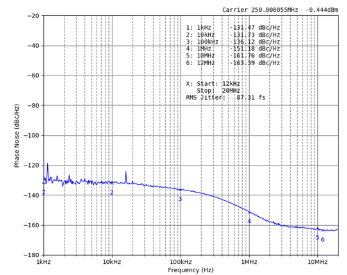
This tool is designed for phase noise measurements. It will return a plot and a summary to the user. The phase noise plot shows phase jitter for a 12 kHz – 20 MHz integration range. The linear vertical scale is in dBc/Hz and the log horizontal scale is in Hz. In addition to the phase noise plots, the user also receives a log file with output type, enable/disable status and output frequency measurement.
Phase noise plot generated by IDT’s Jitter Measurement Utility:

Increased Productivity
The Utility performs the same precise test every time a user submits the setting file and automatically saves the summary log file and phase noise detailed results. Users will not need to perform repetitive, manual measurements and will have more time to spend on other advanced projects.
The Jitter Measurement Utility results will indicate immediately if something is wrong with the configuration or if the performance is not as desired. Using Timing Commander, fixes can be applied quickly and a new configuration can be run again to check those changes.
Designed to Help Board Designers
The Utility lets board designers check the device output performance. When a Timing Commander settings file is reconfigured with different settings, the new configuration can be run again. The designer can do this multiple times to find the best performing, most optimized configuration for the desired set of output clocks.
To try the Jitter Measurement Utility for yourself, go to idt.com/jittermeasurement and upload your settings file.
Technical documentation and collateral covering both the Timing Commander tool and the Utility is available on idt.com at:
