In previous blogs, we looked at some of the peripherals that are available on a typical RA family microcontroller that allow you to create complete autonomous subsystems, managing many of the typical housekeeping and I/O intensive tasks found in a typical microcontroller application. This automating of basic low-level tasks can greatly reduce the demand on the CPU’s time, reduce the number of interrupts that need to be serviced, and often can significantly contribute to reducing the system power consumption.
In this blog, I’d like to look at another more unusual and less understood peripherals available in the RA microcontroller family, the Clock Frequency Accuracy Measurement Circuit or CAC. The Clock Frequency Accuracy Measurement Circuit is designed to enable us to check the accuracy of many of the internal and external clock sources available on the RA microcontrollers by allowing us to automatically reference them against each other, indicating when there is an unexpected deviation from the resulting comparison.
The CAC was originally designed to help us improve the safety and reliability of our systems, by enabling self-test functionality for the clock system, but as you will see, it also has other uses as well.
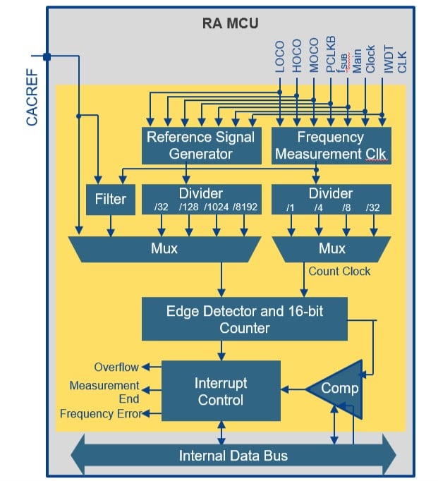
You can see the block diagram of the CAC here.

The CAC allows us to select from a wide range of internal and external clock sources, both as the reference signal and as the target clock which you want to confirm the oscillation speed.
You can typically select inputs from both the main clock and the 32 kHz external clock inputs, for the internal on-chip oscillators, the HOCO, MOCO and LOCO, and the independent watchdog iWDT clock. You can also select PCLKB, the internal peripheral clock as an input. Each clock input, both for the reference clock and the target clock can then be scaled by selecting the appropriate divider ratio.
Each of these clocks can be selected as either as the reference or target clock, you have one additional option for the reference signal, you can also select an external clock input which allows you to input an accurate reference clock from external test equipment.
The reference clock is used as a time base, and the number of clock pulses of the clock to be measured that occur during one cycle of the reference clock is counted in a register. After the measurement period is complete, the number of pulses in the count register is compared to minimum and maximum expected values that are stored in the CAC’s compare registers, and an interrupt can be generated if the clock is detected to be out of range.
This is an ideal method for checking that the calibration of the internal clocks has been set up correctly, or if there is some issue in the initialization of the clock registers that may cause a timing error. The great thing is that once set up, it can operate autonomously, and you can get an interrupt if the system detects an error. You can also generate an error if the counter overflows or at the end of each measurement, as perhaps you only want to use this function occasionally to check the accuracy of various clock sources.
The CAC was designed to support self-test to detect errors with the system clocks, however, it can also be useful for other purposes, especially if we use the external reference pin.
As an example, if you have an external signal, which indicates the health of a system, which changes frequency depending on the system state, the CAC is an ideal solution to measure this signal and detect when it changes frequency. In this case, you effectively use the CAC in reverse, you input your signal to the external reference pin, and select the relevant clock signals, divider settings, and comparator settings to detect an error if your reference signal frequency goes out of range of the “healthy” frequency, so indicating a system error. The CAC can then generate an error if it detects this condition.
The CAC is a useful peripheral that we can use to help check the health of the system, especially useful if you have a consumer or industrial application where system reliability can be very important. Still, as we’ve seen, it can also be used for monitoring external pulse trains and detecting when the frequency of the pulses changes.
