メインコンテンツに移動

概要

説明

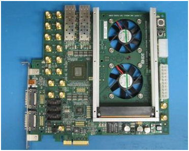
The IDT Tsi721-16GEBI  Evaluation Board is a prototyping platform that leverage’s IDT’s Tsi721 PCIe®  to RapidIO® Gen2 bridge as well as the CPS-1432 RapidIO Gen2 switch, allowing any PCIe processor to communicate to an S-RIO network. The Tsi721-16GEBI Evaluation board has a variety of interfaces that allows customers to interface DSPs, Microprocessors, and FPGAs to IDT switches, and also allows for x86 processors to interface to an S- RIO network through the Tsi721 bridge. Interfaces include AMCs, SMAs, InfiniBand/CX4 and SFP+ connectors. This allows customers to implement most network configurations that represent their production hardware in a logically equivalent manner. By doing so, systems firmware and software engineers can start implementing their code before production hardware is available thereby accelerating development cycles and time to market. 

The Tsi721-16GEBI evaluation board can network together multiple processors in individual PCs. Each PC is populated with a Tsi721 evaluation board. Each evaluation board is networked together over S-RIO, allowing for a cluster of PCIe enabled x86 processors over S-RIO.

The Tsi721-16GEBI evaluation board comes equipped with RapidFET JTAG, a software tool that can configure IDT switches and bridges out of band via the JTAG interface on the board, making access to registers simple via a user friendly Graphical User Interface.

特長

  • Industry-standard system interconnect connectors 
    • One PCIe x4 connector
    • One AMC B+ connector: x4 S-RIO links, Ports 4–7, 8–11, and 17-20 (No support for IPMC and JTAG)
    • Two SFP+ connectors: x1 S-RIO links
    • Two InfiniBand/CX4 connectors: x4 S-RIO links
    • One SMA array (x4 S-RIO link)
  • JTAG and  I2C 
    • JTAG header: 0.1” 10-pin headers
    • I2C header: 0.1” 10-pin header 
    • One I2C EEPROM per S-RIO device 
    • On-board USB to JTAG/I2C converter (FTDI FT2232HL)

アプリケーション

ビデオ&トレーニング

Introduction to Serial RapidIO® (SRIO)

Description

This video presents an educational overview of the RapidIO architecture and ecosystem. The RapidIO architecture is a high-performance packet-switched, interconnect technology for interconnecting chips on a circuit board, and circuit boards to each other using a backplane. This technology is designed specifically for embedded systems, primarily for the networking, communications, and signal processing markets.
 
Serial RapidIO solutions from IDT include switching and bridging products that are ideal for building peer-to-peer multi-processor systems with 100ns latency, low power consumption, and reliable packet termination — all with industry-standard-based support at up to 20 Gbps per port.  IDT's Serial RapidIO solutions are ideal for wireless base station infrastructure, video, server, imaging, military, and industrial control applications.
 
Video presented by Barry Wood, Expert Applications Engineer at IDT. To learn more about IDT's rich portfolio of RapidIO switches and bridges, visit our Serial RapidIO page.


Transcript

Hello, and welcome to RapidIO 101. My name is Barry Wood. I'm an expert applications engineer working at IDT. I have contributed to the RapidIO spec for the past ten years, and I've also been the architect of some of IDT's RapidIO parts. Today I wanted to talk with you a little bit about RapidIO. 
 
Now most of you have probably not heard enough a lot about RapidIO, even though you likely use it every day indirectly. RapidIO is used in a great many of cell phone base stations. So if you use an LTE base station, that base station uses RapidIO technology. It's also likely that if you're using a 3G base station, you're using RapidIO technology. RapidIO is also used largely in military compute, so high-performance mobile compute as well as industrial control and medical imaging. You’ll find that RapidIO excels wherever there are size, weight, and power constraints, and the latest example of that is that RapidIO was selected by NASA and a number of other companies as the next generation Space Center Connect. If RapidIO can meet the size, weight, and power constraints of space, I'm sure it's ideal for your application. 
 
The RapidIO specification is a layered specification consisting of a logical transport and physical layer. The logical layer defines read/write and messaging semantics for use by RapidIO components. The transport layer defines how RapidIO packets are routed through a RapidIO fabric. And the physical layer defines the electrical encoding and electrical characteristics of RapidIO links. There are also a number of RapidIO specification parts that cut across the different layers. I'm going to talk about two of those today. The first is the RapidIO system bring-out specification, which defines how the RapidIO system is initialized, and the part eight error management specification, which finds the fault-tolerance support for RapidIO systems. The RapidIO specification is available in its entirety from www.rapidio.org. There is no charge.
 
This chart shows a little about how the RapidIO specification is mapped to actual devices. The RapidIO ecosystem consists of two kinds of devices: endpoints and switches. Endpoints are devices that originate and process packets. Switches route packages to endpoints. So at the top you can understand that the logical layer specification largely applies to endpoints. In this chart, there is an example of a microprocessor sending a request to a DSP and receiving a response. The transport layer maps largely to RapidIO switch devices. The physical layer specification applies to every RapidIO link. At either end of the link are two link partners, or processing elements. These link partners exchange two kinds of information. The first is packets, and the second are control symbols. The use of control symbols allows RapidIO to guarantee the in-order delivery of packets from an endpoint to their ultimate destination. RapidIO control symbols have a unique capability among interconnect, in that they can be embedded within packets. This gives RapidIO the lowest-latency control path for flow control and error recovery of any interconnect. The transfer of packets is governed by two quantities. The first is the priority of the packet. The second is the acknowledge ID found in the packet, and also carried in control symbols. 
 
Control symbols carry two kinds of information. The first is information that the transmit side sends to the receiver directly. These are things like start of packet, end of packet, or a multicast event control symbol that signals an event has occurred within the RapidIO network. The other kind of information is information that the receiver is sending back to the transmitter. These are things like packet accepted, so a packet was successfully transferred, packet not accepted, so an error was detected, link response, or time stamp. 
 
These message sequence charts give some information about how RapidIO control symbols are used to ensure the reliable, in-order delivery of packets in a RapidIO fabric. The chart on the left shows success case RapidIO packet transfer. You'll note that the packet is delimited with a start of packet and terminated with an end of packet control symbol. That packet is then acknowledged. So with every hop through a RapidIO fabric, each link partner ensures that its link partner receives the RapidIO packet successfully before reusing the buffer for that RapidIO packet. You'll also see that packets can be terminated with a start of packet control symbol. So if you're sending many packets back-to-back, you can save some bandwidth by not sending an end of packet, but instead sending start of packet, packet, start of packet, and so forth. The middle message sequence chart shows how RapidIO flow control works. Most RapidIO devices will send packets to the receiver regardless of how many free buffers the receiver has. If the receiver does not have sufficient buffering to accept the packet, the receiver sends back a retry control symbol, indicating the acknowledgment ID of the packet that is being retried. The transmitter then sends a restart from retry control symbol, acknowledging receipt of the retry, and chooses a higher-priority packet to send. The exchange of control symbols usually takes less than 200 nanoseconds on a RapidIO link. A similar mechanism is used for error recovery, but instead of a retry control symbol the receiver sends a packet not accepted control symbol, indicating that a transmission error has been detected. The transmitter sends a link request control symbol requesting the acknowledgement ID of the next packet that should be sent. The link response contains that acknowledgement ID. Once that link response has been received successfully, packet transmission resumes. Again, the error recovery can occur in 300 nanoseconds or less on RapidIO links. This is far faster than the error recovery that Ethernet, with its end-to-end packet timeouts allows. 
 
This chart contains a little bit more information about priority and acknowledgement IDs. You can peruse that and read it at your leisure. 
 
This chart has a little bit more information about the packet format of RapidIO. You'll see that, just as it is a layered specification so the packet header is also layered with a physical transport and logical layer header. RapidIO packets longer than 80 bytes have an intermediate CRC in them, which allows a receiving endpoint to ensure the integrity of the transport and logical layer headers before they begin to process the packet. This is just one way that RapidIO was designed to minimize latency and maximize the efficiency of packet transfers between endpoints. 
 
The physical layer header is two bytes that actually contain a physical transport and logical layer header within them. The packet priority, as well as the acknowledgement ID are encoded in the physical layer header. The transport type bits, or "TT bits", determine the size of the following trans [audio skips] and the F type determines the packet format for the logical layer header which occurs in the packet. 
 
RapidIO devices are identified using an 8, 16, or 32 bit device ID. Any RapidIO packet contains two device IDs. The first is the destination ID, which is where the packet is being sent to. The second is the source ID, which is where the packet originated from. To route a packet, the destination ID is used to index into a routing table which determines the output port that the switch should send the packet to. Once a packet is received by an endpoint, if the endpoint must create a response for that packet, it simply switches the destination and source ID and sends back the response. I should note that RapidIO also supports multicast, in which case when the switch uses a destination ID to look up the output port, instead of a single port being returned, a bit vector of ports is returned. Every bit in that vector will receive a [audio skips]. 
 
I mentioned earlier that RapidIO supports read/write as well as messaging semantics. This chart contains some information about the read/write semantics, or how the read/write semantics of RapidIO are implemented. RapidIO supports a variety of read, write, automic, and castroherency operations that support RDMA as well as ccNUMA. 
 
RapidIO messaging has several different possible implementations. The first confusingly, is named a messaging packet. This chart gives some information about the format of messaging packets. RapidIO doorbells are much shorter and indicate that an event has occurred in a system. Just like message packets, doorbell packets are designed to minimize the amount of silicon required to successfully receive and process them. For this reason, if there are insufficient resources to accept a doorbell packet at the receiver, the doorbell packet or message packet will cause a logical layer retry to occur. This is different from a physical layer retry, and it allows limited resources of embedded memory to be used exclusively to process RapidIO packets. So RapidIO does not need a lot of SDRAM bandwidth to efficiently and effectively deliver a lot of throughput and guaranteed latency. 
 
Data streaming packets are another mechanism that is used to support messaging semantics. So while messaging packets only support a 4 kilobyte transfer, data streaming packets support up to 64 kilobytes per transaction. Data streaming packets also support many many more queues than messaging packets. So they are ideal for virtualization. Data streaming packets also support extended header flow control. Extended header flow control was designed to manage quality of service in systems that use client-server kinds of architectures as well as publish-subscribe. Extended header flow control allows a client to communicate the degree that its queues are full to a server, and the server can then respond with either a simple X on X off, rate adjustment, or credit based flow control. This allows the server to very tightly control the quality of service, and hence the user experience that the system is delivering.
 
This chart gives some information about the RapidIO system discovery algorithm. It's a very simple recursive algorithm where, for example the microprocessor first determines that it is connected to a switch. Using standard registers, it checks each switch port, what that switch port is connected to. Device IDs are allocated to the devices that are connected, and the switch routing tables are updated. Note that at this point, the memory map of the system does not need to be determined. That is because RapidIO routes packets based on device ID, and not on address. This allows RapidIO to support any system topology. 
 
RapidIO also has support for fault tolerance. If a RapidIO endpoint fails, or a link to that endpoint fails, a RapidIO switch can be configured to detect that failure within nanoseconds. It can also be configured to discard the packets that are destined for that failed endpoint. This prevents a cascade congestion failure from occurring in a RapidIO system, and allows the system host or the secondary host to diagnose and recover from the fault while the rest of the system continues to operate correctly.
 
If you would like more information about RapidIO, please consult any of these companies or of course my own IDT. Thank you very much for your attention, and let's go RapidIO.