Description
VersaClock® 5 is a low-power programmable clock generator with best-in-class jitter performance with less than 0.7psec RMS phase jitter from 12KHz to 20MHz. The highly integrated device consolidates four differential or eight single-ended clock generators and can store up to four different configuration settings, helping to minimize board space and bill-of-materials. The high-performance clock generator operates at less than 100mW core power (50 percent lower than competing devices), helping to ease system thermal constraints and reduce operating power expenses.
VersaClock 5 can take a crystal or a clock input. It has 4 fractional output dividers which allow the programming of 4 independent frequencies up to 350MHz. The four universal output pairs are independently configurable as HCSL, LVPECL, LVDS, or dual LVCMOS outputs. It also features a reference clock output. The fractional output dividers driving each output pair are easily programmed via I2C while the device is operating in the system, lending itself to system tuning and margin testing. Unlimited in-system reprogramming is possible via I2C, whereas four banks of one-time programmable non-volatile memory provide flexibility for multi-project inventory consolidation or design changes in field or production units. Upon request, devices may be factory-programmed to the customer's desired configuration.
Presented by Baljit Chandhoke, Product Marketing Manager at Integrated Device Technology, Inc. To learn more about Renesas's VersaClock programmable clock generators, visit our page.
Transcript
Hello, my name is Baljit Chandhoke and I’m the Product Marketing Manager of Timing Products at IDT. Today, I will give you a brief introduction of our new low power programmable clock family, VersaClock 5.
VersaClock 5 is a low power, programmable clock generator with best in class jitter performance with less than .7ps RMS phase jitter from 12KHZ to 20MHz. The highly integrated device consolidates four differential or eight single-ended clock generators and can store up to four different configuration settings, helping to minimize board space and bill of materials. It also has a buffered reference clock output.
The high performance clock generator operates at less than 100mW core power, 50% lower than competing devices, with typical total device power of 300mW with all outputs operational, helping to ease system tunnel constraints and reduce operating power expenses. VersaClock 5 has four universal output pairs. Each output pair can be configured as HCSL, LVPECL, LVDS, or two LVCMOS outputs. VersaClock 5 has in-system, programmable clock generator via I2C as well as IDT’s Timing Commander Software.
This slide shows the block diagram of VersaClock 5. VersaClock 5 can take a crystal or clock input. It has four fractional output dividers, which allow programming of four independent frequencies, up to 350MHz. The four universal output pairs are independently configurable as HCSL, LVPECL, LVDS or dual LVCS outputs. It also features a reference clock output. The fractional output dividers driving each output pair are easily programmed via I2C, while the device is operating in the system, enabling system tuning and margin testing. Unlimited in-system reprogramming is possible via I2C, whereas four banks of one-time programmable non-volatile memory provide flexibility for multi-project imagery consolidation or design changes in field. Upon request, the devices may be factory programmed to customer’s desired configuration.
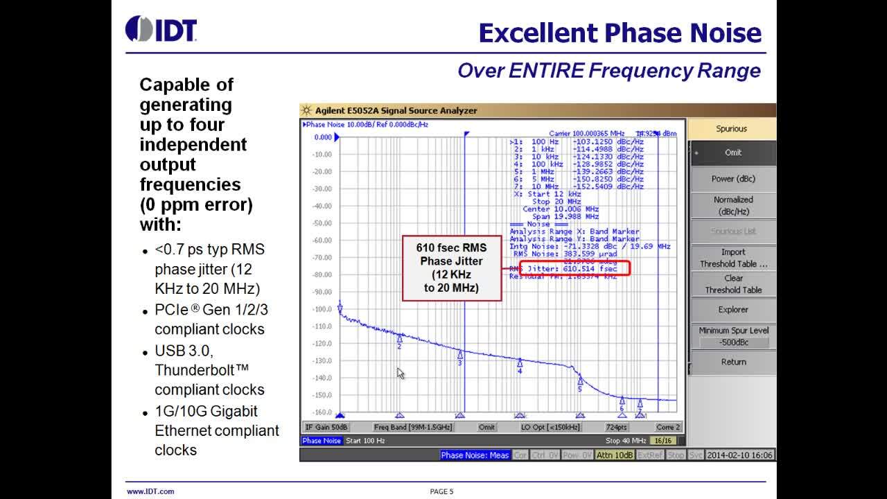
VersaClock 5 has excellent phase jitter performance with 610fsec RMS phase jitter, as shown on the phase noise plot. With RMS phase jitter less than .7ps or the full 12KHz to 20MHz integration range, the new device meets the stringent jitter requirements of PCI Express Gen 1, Gen 2, and Gen 3, as well as USB3.0 and 1G/10G Ethernet.
IDT’s new Timing Commander Software platform enables customers to configure program VersaClock 5 with an intuitive and flexible graphical user interface, as you see on the slide. You can program the four fractional output dividers, providing four independent output frequencies with 0 ppm error. You can configure universal output pairs as differential LVDs, HCSL, LVPECL, or two single unit outputs, as well as program each output independently with spread spectrum, if needed.
VersaClock 5 is useful in high-end consumer applications, networking applications, computing applications, industrial communications, broadcast radio and medical applications.
The block diagram shows a typical application of VersaClock 5, which has a 125 LVPECL output for gigabit Ethernet, a 156.25MHz LVDS output for 10 gig Ethernet and a 100MHz HCSL output for PCIe Gen3, as well as a 25MHz reference output. With all the different outputs operational and the cross-talk – including the cross-talk, we get 700fsec integrated phase jitter from 12KHz to 20MHz. The key application issues solved by VersaClock 5 are shown on the slide.
In summary, VersaClock 5 is a low-power, programmable clock generator with best-in-class performance and design flexibility. It has excellent phase jitter performance. Our wide range of frequencies provides design flexibility with less than .7ps RMS phase jitter from 12KHz to 20MHz. VersaClock 5 has significantly less power consumption, which enables easing thermal constraints in the system. IDT VersaClock 5 programmable clocks are ideal clocking solutions for a wide range of applications replacing crystal oscillators, clock generators – allowing for in-system programming, saving BOM and board space, as well as improving time to market and shortening design time. IDT VersaClock 5 provides industry’s most versatile, low-power clock generation solution for consumer, computing, industrial, communications and networking applications.
We have complete product support for VersaClock 5. We have a product brief, product data sheet, programming guide, elevation board with user’s manual, Timing Commander Software with user’s manual, product radio reference schematic available at the link shown on the slide.
Thank you for your time.
