In my last two blogs, I looked at some of the unique peripheral functions available on our RA Microcontrollers; we looked at the Data Operating Circuit (DOC) where we saw how the DOC can be used to make simple decisions, and we looked at the Data Transfer Controller (DTC).
Now we have seen how the basic functions of the DOC and DTC function, we can look at a simple system example to understand how we can use these functions to cerate a complete, autonomous subsystem, that can operate without CPU intervention
The system we want to create is a simple multiple input level detector, which uses the group scan mode of the 12-bit ADC to sample each of 4 input signals in turn and using the combination of the DTC and the DOC, detects if a programmable threshold level is exceeded, and only if this value has been exceeded, the system will generate an interrupt and waken the CPU.
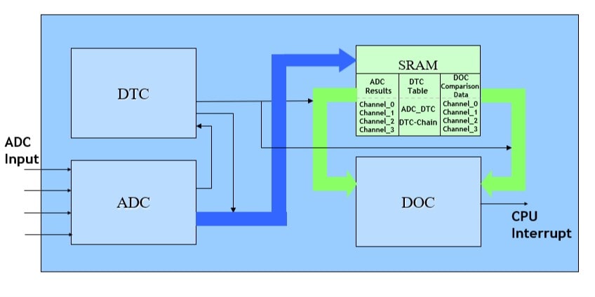
After the initial system setup, the CPU goes to sleep to save power, and only awakens if an interrupt from the DOC occurs, indicating that the threshold has been exceeded. A simplified system diagram is shown below.

In group scan mode, the ADC continuously samples each input in turn, and copies the result into SRAM. When all 4 inputs have been samples, the ADC generates a DTC request. Using chain mode, this request starts a chain of 8 transfers between memory and the DOC, copying from the on-chip SRAM, , both the 4 ADC results, and a corresponding threshold value that each ADC result should be compared again.
ADC transfer request to DTC.
DTC transfer 1 Comparison[0] to DOC. Chain Enabled, so do next transfer
DTC transfer 2 AN000 to DOC Chain Enabled, so do next transfer
DTC transfer 3 Comparison[0] to DOC Chain Enabled, so do next transfer
DTC transfer 4 AN001 to DOC Chain Enabled, so do next transfer
DTC transfer 5 Comparison[0] to DOC Chain Enabled, so do next transfer
DTC transfer 6 AN003 to DOC Chain Enabled, so do next transfer
DTC transfer 7 Comparison[0] to DOC Chain Enabled, so do next transfer
DTC transfer 8 AN005 to DOC Chain Disabled, so stop
In this case, we initialise the DOC to compare each value and generate and generate an interrupt if any of the threshold values are exceeded.
Once the ADC, DOC and DTC are initialised, each ADC input is checked continuously in the background, without any CPU intervention. The CPU can manage other tasks or even be placed in sleep and will not waken up until one of the inputs exceeds the relevant value.
Many other low-level tasks can be automated by the combination of DOC and DTC in much the same way. This can be an extremely powerful technique to automate low level functions and can both save development time and cost in developing low level software drivers for these tasks, as well as improving system performance by automating the basic functions without the need for any CPU involvement.
Every member of the RA microcontroller family includes intelligent peripheral features like the Data Operation Circuit and the Data Transfer Controller along with many other power peripheral functions which can also be used to create intelligent subsystem. Together the DOC and DTC provide highly flexible and powerful solutions to automating low level I/O functions in many different applications. The automation of these low-level functions not only improves the system response time to real time events but can often reduce system software complexity and software size, so increasing reliability and reducing system test costs.
The RA Microcontroller family is aimed at a wide range of communications and control applications such as motor control, smart sensors, metering, hand-held instruments, low power modems and many other industrial and consumer applications and comes in a wide range of memory size and package options. For more information visit www.renesas.com/ra.
