概要
説明
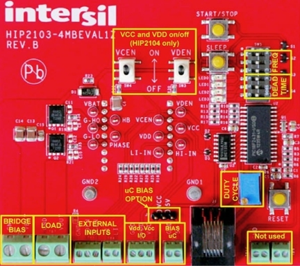
The HIP2103_4MBEVAL1Z is an evaluation tool for the HIP2103 and HIP2104 half bridge MOSFET drivers. This tool consists of a mother board and HIP2103DBEVAL1Z and HIP2104DBEVAL1Z evaluation daughter cards. The motherboard platform provides an on-board microcontroller that is used to generate appropriate control inputs to the HIP2103 or HIP2104. The frequency, the PWM duty cycle, and the dead-time provided by the microcontroller are user adjustable.
特長
- 60V maximum bootstrap supply voltage
- 3.3V and 12V LDOs with dedicated enable pins (HIP2104)
- 5µA sleep mode quiescent current
- 4V undervoltage lockout
- 3.3V or 5V CMOS compatible inputs with hysteresis
- Integrated bootstrap FET (replaces traditional boot strap diode)
アプリケーション
- Half bridge, full bridge and BLDC motor drives
- UPS and inverters
- Class-D amplifiers
- Any switch mode power circuit requiring a half bridge driver
設計・開発
ソフトウェア/ツール
製品選択
適用されたフィルター
ビデオ&トレーニング
This video demonstrates the HIP2103 and HIP2104 half bridge drivers designed for three-phase, brush-less DC motors or other applications with similar loads.
Transcript
Hello, my name is Richard Garcia. I'm the factory applications engineer for bridge drivers. This year, we're highlighting a couple of new parts that were designed specifically for battery-powered tool applications or any application that is battery-powered.
This product is the HIP2103 and the HIP2104. It has some unique features that are very important to battery applications. One of which is very low bias current. We have a technology that allows us to implement Sleep mode without needing a separate enable pin. The smaller package, the HIP2103 is in an 8-pin, 3mm x 3mm DFN package which is about as small as you can get, which is important for applications such as handheld tools that require very small area.
The HIP2104 is also exactly the same as the HIP2103 except that it also has two internal voltage regulators. One regulator operates at 12V. The other regulator operates at 3.3V. The 12V is used to provide the bias for the driver section itself, and the 3.3V is used to provide the bias for the external controller.
In a typical application such as the BLDC three-phase motor, you would use one HIP2104 to provide the bias, and you would then use an additional two other HIP2103s to provide the three-gate drives that are necessary for a BLDC motor.
This demo board that we have utilizes all two drivers, the HIP2104 and two HIP2103s. We use the daughter card for the controller so that if you desire to evaluate our drivers but with your own controller, it's easy to replace the daughter card with your own controller, using whatever method you wanna use. This product has been operating for three days now off of a 20V battery, and of course, we don't have a very heavy load but this is a good example of how power efficient you can be with a BLDC motor.
Also available with the demo board or independently if you like, we have an application note that covers in quite a bit of detail, the basics of how a three-phase BLDC motor operates. We also have a datasheet. Both of these products are released and in production.


