概要
説明
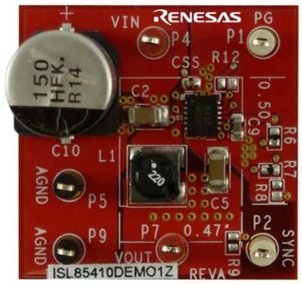
The ISL85410DEMO1Z board is intended for use in point-of-load applications sourcing from 3V to 40V. The boards are used to demonstrate the performance of the ISL85410 wide VIN, low quiescent current, high-efficiency synchronous buck regulator with 1A output current.
The ISL85410 1A synchronous buck regulator provides an easy-to-use, high efficiency low BOM count solution for a variety of applications. The ISL85410 integrates both high-side and low-side NMOS FETs and features a PFM mode for improved efficiency at light loads.
特長
- Wide input voltage range: 3V to 40V
- Synchronous operation for high efficiency
- No compensation required
- Integrated high-side and low-side NMOS devices
- Selectable PFM or forced PWM mode at light loads
- Internal fixed (500kHz) or adjustable switching frequency 300kHz to 2MHz
- Continuous output current up to 1A
- Internal or external soft-start
- Minimal external components required
- Power-good and enable functions available
アプリケーション
- Industrial control
- Medical devices
- Portable instrumentation
- Distributed power supplies
- Cloud Infrastructure
設計・開発
ソフトウェア/ツール
ビデオ&トレーニング
See how easy it is to design with Intersil's new pin-for-pin compatible synchronous buck regulators with a wide input voltage range. With three different output current options, these highly efficient sync buck regulators simplify power circuit design and enable reuse of circuit board design across a wide range of end applications.
Transcript
Hi, my name is Paul Orfanu, I'm an application engineer for Intersil. I'm going to introduce ISL85415 that will help you simplify your design while maintaining similar efficiency or better than standard buck regulators. This one is a synchronous buck regulator, and let me show how this topology works. This is the block diagram that you may find on the datasheet. We have the two upper and lower FET integrated, which eliminates the the needs for external drivers. And also, we have integrated the compensation. It could be internal compensation or external compensation. That also eliminates the need for components.
In order to have performance optimization, we also have the frequency that also can be adjustable. By looking at the performance of efficiency, we have optimized the curves that indicates at light load our efficiency can go up to 95%. And in heavy load, it's also maintaining to reduce oscillation of the output FETs, integrated FETs. So while I'm integrating them, we'll also ensure a very good performance, by minimizing their oscillation. Going back to the topology, because of the peak current mode control pulse with modulation architecture, there is also a fast transient response that this part can have, can ensure. Also, the part has synchronization, as a sync pin. If the sync pin is tied high, that can ensure PWM, forced PWM operation. If the sync pin is tied low, then there will be a forced PFM.
However, the part will have a very good transition, PFM to PWM, because of this architecture. Also, in PWM mode the frequency can be internal, D4 500kHz, while external selectable from 300kHz to 2MHz optimized component inefficiency. And also output voltage is selectable from 0.6V all the way to 95% of the input voltage. Quiescent current is also very low on the part, as well as shutdown current. Enable and power-good are also additional added features. That is also explained in the data sheet. All these features and calculations are explained in the application note and data sheet. You might refer to them.
Because of its wired input voltage range, eight out of ten design engineers would have a need to use this part in their application, from consumer devices to industrial markets.


