In this short series of Reducing Noise Issues in Microcontroller Systems blogs, we have looked at noise and how it can disturb the operation of microcontroller-based systems and presented some of the "rules" we can use to minimize the impact of noise in our systems.
Due to the popularity of this series of blogs, we have decided to add this blog as a bonus "extra" to look at some of the features of our RA microcontrollers that can help make a system more reliable in the presence of noise.
In any system, the best way to avoid noise problems is to consider noise reduction from the beginning of the design. It’s important to understand the environment that your system will operate in, what noise sources will be present, and what steps you can take to mitigate these.
It’s always worth spending some time to consider these issues at the start of the design, as it’s much easier to design noise mitigations from the start than to add them at the end of the design, or even worse, have to modify your design when you discover noise problems in the field.
However, sometimes it’s not possible to completely remove every source of noise, and Renesas RA microcontrollers offer a range of features that can help you make your applications more robust.
In any microcontroller we have to take great care of the system's pins, these are pins that are intrinsic to the operation of the device, and include the supply pins (Vss, Vcc, Vcl, etc.), clock pins, the reset pin, any analog reference pins, the debug pins, and the mode pin (used for controlling the operating mode of the device, such as the boot mechanism).
Each of these pins should receive special consideration in the PCB layout to make sure they operate reliably, as noise on these pins could be fatal for your application.
As we’ve already discussed in previous Reducing Noise Issues in Microcontroller Systems blogs, a good PCB layout is critical in reducing noise, and great care needs to be taken in the design of the power supply and ground system, especially as today's MCUs are typically capable of much faster operation than older devices. Carefully consider the circuit layout, and consider ground return paths, especially for high-speed, high-current signals.
One of the first issues I always ask when I hear about noise issues in a design is do you really need to run so fast, sometimes you need your device to run at maximum speed, but often you do not. The maximum speed may be dictated by the baud rate you need for your UART or by the time you have to complete a Fast Fourier Transform (FFT) filter function, however much of the time, and for many designs, we don’t need to run at the full speed the device is capable of.
We would always recommend that you run as slow as you can to achieve everything you need to achieve and not faster; the faster you go, the faster the signals and the more problems you may have. The slower you go, the less current you take, the less current is switching in your power supply, and the less noise is generated. And, sometimes your power supply will be cheaper because of this. For some things, slower is almost always better.
The RA microcontrollers have the capability to "throttle" their speed, you can change the clock dividers dynamically if required to speed up and speed down. This can sometimes add a lot of complexity to an application as you have to manage the peripheral clocks, but it’s always worth considering if you can reduce the clock speed.
And talking of power supplies, always make sure the power supply's dimensions are correct for your design, don’t always try to reuse the same power supply circuit, and make sure it’s capable of supplying the maximum amount of current you require, as if your supply droops occasionally, this can cause noise issues as well as can generate other system problems.
The datasheet of the RA family carefully documents the capability of each of the I/O pins on each of these devices, there is also a very useful application note available on the Renesas website that details the injection current our devices can withstand to prevent damage to the RA MCU.
Typically most of the standard digital I/O pins (5V tolerant pins on 3V devices, or devices supporting I2C or some other special functions that do not have Schmitt trigger input) on the RA microcontrollers have Schmitt trigger inputs, which can help us make sure fast signal level changes do not propagate into the logic of our device. It’s important to consider the current that will be flowing into and out of the pin, both in normal operation, and if noise is present in the system, the use of current limiting resistors on I/O pins can sometimes be advisable to limit these effects, even external filtering or a protection circuit may be required in extreme cases.
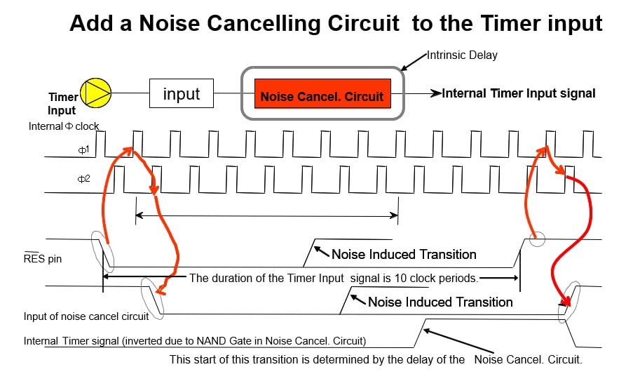
Many peripheral input pins also have programmable noise filters, these are commonly found on communication peripherals such as UART, SPI, and I2C interfaces as well as many timer inputs. The correct choice of filer clock selection is important to get the best performance out of these filters, often some trial and error are required to achieve this.

Communication interfaces are one of the biggest problem areas of a typical microcontroller design, as by nature, they are connected to the outside world and often bring high-speed signals into the system. Great care should be taken here, and the use of external protection circuitry is often advisable depending on the nature of the external environment.
We have discussed the importance of good clock system design before in a previous blog titled "Creating Reliable Crystal Oscillators Circuits for Your MCU Design", but again we would like to emphasize that it’s very important if you are using external crystals, to make sure they are correctly matched to your PCB design and to the device. This is especially true if you are using a low-speed, 32kHz oscillator, as these are notoriously prone to problems in noisy environments. We always recommend you check with your oscillator supplier for the correct matched circuit to operate with our devices. A stable oscillator circuit with a lot of margins is much less likely to cause problems.
Watchdog timers are an excellent method of recovering your application when noise causes a system's crash, However, it’s important to consider how to use these correctly.
On RA microcontrollers, watchdog timers come in two flavors, the standard watchdog timer which can be clocked from a number of the standard clock sources on the microcontroller. This watchdog is typically used to check the application’s code execution and to detect any malfunction or unexpected operation. It’s typically switched off during low-power applications. This watchdog can generate a RESET or an interrupt when it times out.

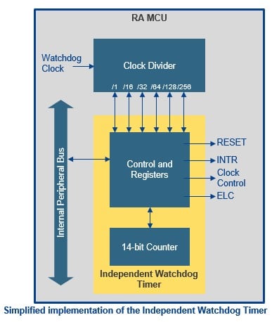
The second watchdog timer is the Intelligent Watchdog Timer (iWDT), this WDT uses a dedicated low-speed on-chip oscillator as its clock source allowing a long time out and also allowing independent operation from the normal CPU clocks, so even if the CPU clock fails, the iWDT will still cause a reset or an interrupt after it times out. A simplified block diagram of the iWDT is shown above.
Each of the watchdogs can operate with a "window" function, where a "tickle" that occurs too early as well as the watchdog timing out can cause a reset. Each watchdog can be selected to auto-start after a reset by setting the relevant bits in the option function select register, a flash-based register that holds initialization data for the device.
A common mistake we often see is to place the watchdog "tickle" inside an interrupt service routine, as this is considered efficient, as only one instance is normally required. However, this can be dangerous, as while the main application may crash, the interrupt system may continue to operate, so negating the watchdog.
When your application is complete, you should analyze all the possible execution paths. This can be difficult for complex applications using an OS, but modern code analysis tools integrated into modern development tools can help here.
Then you should place multiple instances of the watchdog tickle at relevant locations throughout the application, this will make the application much more reliable, and have the added advantage that it will detect if the application takes an unexpected execution path which is normally an indication of a serious issue such as a system rash or a pointer overflow.
We’ve already mentioned low-power applications, and the use of watchdog timers in low-power applications also needs special consideration. You should consider carefully what happens when the system is placed in low power.
These are just some of the features of our RA microcontrollers that are designed to make your system more reliable. In previous Reducing Noise Issues in Microcontroller Systems blogs, we have covered functions such as the Data Operating Circuit and the ECC SRAM which can also be used to make your systems more reliable in a noisy environment by detecting if there is some problem with the on-chip memory. We also have features such as Trustzone® and the on-chip Memory Protection Units, which can be used to detect unauthorized or unexpected access to secure memory and peripherals which can also be an indication of systems failure.
I hope you’ve found this blog useful and have pointed you to some of the features in our devices that may help you make a more reliable application.
Related Blogs
Reducing Noise Issues in Microcontroller Systems - Part 1
Reducing Noise Issues in Microcontroller Systems - Part 2
Reducing Noise Issues in Microcontroller Systems - Part 3


