概要
説明
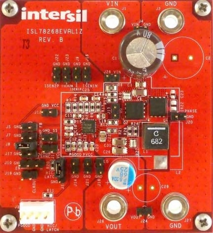
The ISL78268EVAL1Z is a fully configured buck converter evaluation board that includes an ISL78268 synchronous buck controller, MOSFETS, an inductor, current sense resistors, and other necessary components. The evaluation board has been designed to evaluate the features and performance of the ISL78268 quickly and easily.
ISL78268 is an automotive-grade synchronous buck controller with the 2-A sourcing/3-A sinking integrated MOSFET drivers used in automotive and industrial applications. The device supports a wide input supply voltage range of 5V to 55V for full operation and protected up to 60V when not switching.
特長
- Wide operational input voltage range up to 55V (switching), withstand 60V (non-switching)
- Average output constant current limiting
- Selectable diode emulation mode or forced PWM mode
- Selectable switching clock source: internal or external
- Low shutdown current: IQ <10µA
- Selectable latch-off or hiccup mode fault response
- Comprehensive fault protections:
- Input and output overvoltage protection
- Cycle-by-cycle overcurrent limit (OC1) and protection (OC2)
- Average current overcurrent protection
- Over-temperature protection
アプリケーション
- Automotive power
- Telecom and industrial power supplies
- General purpose power
- Supercap charging
ドキュメント
|
|
|
|
|---|---|---|
| 分類 | タイトル | 日時 |
| マニュアル-開発ツール | PDF 1.40 MB | |
| データシート | PDF 7.78 MB | |
| データシート | PDF 2.10 MB | |
3件
|
||
設計・開発
ソフトウェア/ツール
製品選択
適用されたフィルター
ビデオ&トレーニング
Learn how to set up and use the ISL78268 55V synchronous buck controller and evaluation board.
Transcript
Hi, I'm Ed Kohler, Marketing Manager for Intersil's Automotive Power Management Products. Today I'd like to introduce you to the ISL78268, a 55V synchronized buck controller. Then I'd like to demonstrate how easy it is to order and use the evaluation board.
The ISL78268 is a fully synchronous buck controller. What stands out about the ISL78268 is its versatility. It integrates a unique set of features I think you'll find very valuable. Some of those features are: a 5V to 55V input range, integrated 3A drivers with adaptive dead-time control, optional constant current regulation, a selection for light load operation between forced PWM mode for low noise or diode emulation mode for improved efficiency. And it also has a comprehensive set of protection features that includes the ability to select between latch-off or hiccup fault response.
The ISL78268's evaluation board is a great way to try out any of these features. It’s easy to order and to use. To get one, you just need to visit the ISL78268's page on our website. Just click over to the order tab and then scroll down to find the evaluation board's part number. That's ISL78268EVAL1Z.
When the board arrives, this is what you should get. Inside, you'll find the ISL78268 evaluation board along with documentation. There will be a user guide for the evaluation board and a datasheet for the ISL78268. To get started, all we need is a power supply, a load and some cables. So, I'm using a dual 30V supply that I've set to operate in series mode so I can deliver up to 60V to the input because I want to check out the ISL78268's wide input voltage range. And I've preset my load to 5A so that should do it. Let's get started.
Okay, let me show you what I've done here. First, I installed jumpers at J28 and J10. This allows the part to automatically be enabled when the input supply comes up. Then I connected my upper meter to the input voltage monitoring test point and I connected my lower meter to the output voltage monitoring test point. Then I connected my supply to the input voltage and my load to the VOUT terminals. Now, if I enable the supply...you can see I've set it up for 48V so I'm regulating 48V at the input to 12V at the output. Now, if I enable the load, we see that we maintain the 12V regulation, as you'd expect.
Now, I also have put an oscilloscope probe on the phase node so that we can see the switching action. If we look at the oscilloscope, we see that we're switching at 300kHz which is default and the phase node is going between ground and being at 48V, as we'd expect. Here I can demonstrate the overvoltage response at the input.
So if I increase the input voltage to over 55V, at typically around 58V the overvoltage protection will kick in and stop the part from switching. And there we have it, stop switching. Now, if we allow the voltage to come back down below the overvoltage threshold, we see that the switching starts again and we're regulating again at 12V. The evaluation board lets you check out all the features of the ISL78268, and don't worry, the documentation will walk you through how to do all of that.

