Features
- 120MHz RXv2 core (5.05 CoreMark/MHz*1), single-precision FPU
- 2.7V to 3.6V operation, single power supply
- Operating temperature: -40°C to 85°C or -40°C to 105°C
- Large-capacity memory: 2MB code flash, 640KB SRAM
- Dual-bank function convenient for firmware updates*2
- 32KB data flash that can store data like an EEPROM
- Diverse package lineup from 100 to 176 pins
- Up to 136 general-purpose I/O ports
- USB 2.0 Host/Function/OTG (supports full speed (12Mbps), low speed (1.5Mbps), and isochronous transfer)
- CAN (ISO 11898-1 compliant, up to 1Mbps transfer)
- SD Host I/F (supports SD memory/SDIO 1-bit or 4-bit SD bus)
- SD Slave I/F (SDIO Card Spec. Ver. 2.00 compliant)
- QSPI (XIP mode not supported)
- Various other communication interfaces (SCI, IIC, RSPI, etc.)
- 16-bit PWM timer, 16-bit/32-bit compare match timer, 8-bit timer, RTC
- 12-bit A/D converter, 12-bit D/A converter, temperature sensor
- TFT-LCD controller and 2D drawing engine can reduce CPU load at running of LCD display
- Security
- Memory protect functions that protect Flash memory from unintended access to flash
- Trusted Secure IP enables high level of Root of Trust*2
- AES, TRNG*2, RSA*2, and SHA*2 encryption engines
*1: Typical for RXv2 core
*2: Only products with 1.5MB or more code flash memory


Description
The Renesas RX651 is mainstream RX microcontrollers with RXv2 core, large-capacity RAM, and enhanced security, connectivity and human machine interface (HMI) capabilities.
Parameters
| Attributes | Value |
|---|---|
| Main CPU | RXv2 |
| Program Memory (KB) | 512, 768, 1024, 1536, 2048 |
| RAM (KB) | 256, 640 |
| Carrier Type | Bulk (Tray), Full Carton (Tray), Tray |
| Supply Voltage (V) | 2.7 - 3.6 |
| I/O Ports | 43, 79, 112, 137 |
| DRAM I/F | No, SDRAM I/F |
| Temp. Range (°C) | Ta = -40 to +85, Ta = -40 to +105 |
| Operating Freq (Max) (MHz) | 120 |
| Ethernet speed | No |
| Ethernet (ch) | 0 |
| EtherCat (ch) (#) | 0 |
| USB FS (host ch/device ch) | ( 0 / 1 ), ( 1 / 1 ) |
| USB HS (host ch/device ch) | ( 0 / 0 ) |
| USB SS (host ch/device ch) | ( 0 / 0 ) |
| SCI or UART (ch) | 9, 11, 13 |
| SPI (ch) | 11, 14, 16 |
| I2C (#) | 11, 13, 14, 15, 16 |
| CAN (ch) | 0, 2 |
| CAN-FD (ch) | 0 |
| Wireless | No |
| SDHI (ch) | 0, 1 |
| High Resolution Output Timer | No |
| PWM Output (pin#) | 25, 38, 39 |
| 32-Bit Timer (ch) | 3 |
| 16-Bit Timer (ch) (#) | 18 |
| 8-Bit Timer (ch) | 4 |
| Standby operable timer | No |
| 12-Bit A/D Converter (ch) | 10, 22, 29 |
| 24-Bit Sigma-Delta A/D Converter (ch) | 0 |
| 16-Bit D/A Converter (ch) | 0 |
| 12-Bit D/A Converter (ch) | 0, 1, 2 |
| 8-Bit D/A Converter (ch) | 0 |
| Capacitive Touch Sensing Unit (ch) | 0 |
| Segment LCD Controller | No |
| Security & Encryption | Unique ID, Unique ID, AES, 3DES, RSA, ECC, SHA-1, SHA224/SHA256, MD5, MAC, TRNG, Unique ID, AES, TRNG |
Package Options
| Pkg. Type | Pkg. Dimensions (mm) | Lead Count (#) | Pitch (mm) |
|---|---|---|---|
| LFBGA | 13 x 13 x 1.4 | 176 | 0.8 |
| LFQFP | 10 x 10 x 1.7 | 64 | 0.5 |
| LFQFP | 14 x 14 x 1.7 (PLQP0100KB-B) / 14 x 14 x 1.6 (PLQP0100KP-A) | 100 | 0.5 |
| LFQFP | 14 x 14 x 1.7 | 100 | 0.5 |
| LFQFP | 20 x 20 x 1.7 | 144 | 0.5 |
| LFQFP | 24 x 24 x 1.7 | 176 | 0.5 |
| TFBGA | 4.5 x 4.5 x 1.2 | 64 | 0.5 |
| TFLGA | 7 x 7 x 1.05 | 100 | 0.65 |
| TFLGA | 7 x 7 x 1.05 | 145 | 0.5 |
| TFLGA | 8 x 8 x 1.05 | 177 | 0.5 |
Application Block Diagrams
 | Voice Over PLC with High-Performance Audio Codec Power line communication enables audio transmission without extra cables, reducing cost and complexity. |
 | Power Sequencer & I/O Expander for Printers (PPC/MFP) An MCU-based power sequencer and I/O expander for high-performance PPC/MFP printers. |
 | Torque Control System Precision torque control ensures product quality using MCUs with high-precision AFE and reliable sensors. |
 | 400ZR Optical Module Optimize 400Gb Ethernet transport over DCI links with a compact 400ZR module for high performance and low power. |
 | Tiny Flexible System-on-Module (SoM) This flexible SoM integrates an MCU, FPGA, and programmable mixed-signal matrix onto a single board. |
 | Motor Control with Resolver Resolvers enhance motor control precision, reliability, and reduce costs in stepper and BLDC motor systems. |
 | Smart Lock with Ultra-Low Power Wi-Fi & Bluetooth Low Energy Low-power smart lock system enabling secure, wireless control with fingerprint support. |
 | Electronic Lock with Fingerprint Identification |
 | Voice Over Power Line Communication Renesas' PLC modem technology enables efficient voice transmission over low-voltage power lines. |
 | Power Line Communication (PLC) Node PLC Node system supports G3/PRIME standards for smart building communication. |
Complete Your Design
Explore complementary products to elevate your design
Renesas Boards & Kits
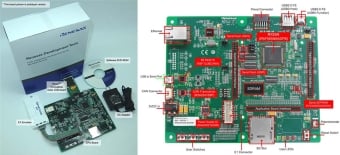
Renesas Starter Kit+ for RX65N-1MB
The Renesas Starter Kit+ for RX65N is the perfect starter kit for developers who are new to the RX65N. The kit includes an LCD display module, on-chip debugging emulator, and integrated development environment so you can start evaluating the RX65N immediately after opening the box. Please use... Read More

Renesas Starter Kit+ for RX65N-2MB
The Renesas Starter Kit+ for RX65N-2MB is the perfect starter kit for developers who are new to the RX65N (Code Flash 2MB, Pin Count 176-pin). The kit includes an LCD display module, on-chip debugging emulator, and integrated development environment so you can start evaluating the RX65N... Read More

RX65N Envision Kit
The Envision Kit allows quick and easy evaluation of the RX65N microcontrollers group, which is an excellent choice for your next low cost HMI (Human Machine Interface) project. Moreover the RX65N Envision Kit allows you to experience, through pre-installed demos, firmware updating using the new... Read More

Target Board for RX65N
The Target Board for RX65N provides an entry point to evaluation, prototyping and developing for the RX65N MCU. Moreover, since this board incorporates an emulator circuit, you can use it for your own application design without the need for further tool investments. This product provides... Read More

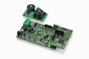
CPX3 Evaluation Kit for DC under 48V (J80D1 with RX651+Audio circuit)
The Renesas CPX3 Evaluation Kit J80D1 is a power line communication (PLC) evaluation kit for direct current (DC) power lines that can be used to carry out software development and system evaluation using the R9A06G037 PLC modem IC. This evaluation kit supports audio communication solutions. Two... Read More
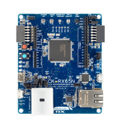
Cloud Kit Based on RX65N MCU Group
The CK-RX65N cloud kit enables users to securely connect to the cloud and explore the features of the Renesas RXv2 core based RX65N MCU Group and cloud services.
With multiple network connectivity options, the kit provides a seamless cloud connectivity experience to most of the global cloud... Read More

Hybrid PLC and Sub-GHz Communication Evaluation Kit
This product is an evaluation kit for developing software and evaluating systems compatible with Renesas' Power Line Communication (PLC) modem IC R9A06G037 and Renesas’ Sub-GHz wireless IC RAA604S00. This kit can be configured to support many configurations, PLC only R9A06G037, Hybrid (PLC & RF)... Read More

Industrial Automation Functional Safety Evaluation Boards Featuring RX MCUs
The industrial automation functional safety reference board enables evaluation of Renesas safety software and contains detailed design and safety analysis based on Renesas’ experience in safety system specifications and implementation. This reference board can be used as a template to shorten... Read More
CPX4 DC-PLC Evaluation Kit M01D1
This product is an evaluation kit for DC-based power line communication for developing software and evaluating systems compatible with Renesas' PLC modem IC R9A06G061. This product is a complete evaluation platform comprising the analog front end and control MCU required for DC power line... Read More

CPX4 AC-PLC Evaluation Kit M02D2
This product is an evaluation kit for AC power line communication for developing software and evaluating systems compatible with Renesas' PLC modem IC R9A06G061. This product is a complete evaluation platform comprising the analog front end and control MCU required for AC power line... Read More
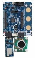
Smart Lock with AWS IoT Development Kit
The demand for smart locks is a rapidly growing segment for the home and building automation industries. This smart door lock solution features fingerprint control and low-power Wi-Fi, providing convenient fingerprint recognition, as well as on-site and remote lock open/close. The solution uses... Read More
Test This Board Remotely
Partner Boards & Kits
AP-RX651-0A
RX Family Microcontroller Board
Filters
Software & Tools
Filter by Type
Filter by Provider
Sample Code
Filter by Application
Filter by Function
Filter by Compiler
Filter by IDE
Simulation Models
Partner Solutions
- Software PackageDevice driver set for the RX Family (including major middleware). Target devices : RX130, RX23W, RX231, RX24U, RX64M, RX65N, RX66T, RX71M, RX72M etc.
- IDE and Coding ToolRenesas integrated development environment (IDE) [Support MCU/MPU: RH850, V850, RX, RL78, 78K0R, 78K0] (Note: CS+ is not generally promoted to U.S. and European customers.) (Note: To use Smart Configurator on CS+ for RL78/G23 and RX family MCUs, install the Smart Configurator for each MCU family separately downloading from ”Design & Support” > ”Development Tools” > ”Smart Configurator”)
- IDE and Coding ToolEclipse-based Renesas integrated development environment (IDE).
- IDE and Coding ToolRenesas IAR Embedded Workbench Device-Support-Packages include all device-specific files to be used with the Embedded Workbench IDE.
- Compiler/AssemblerC/C++ Compiler Package for RX Family [IDE: CS+, e² studio, High-performance Embedded Workshop]
- Solution ToolkitThis development assistance tool supports the development of embedded systems which use the LCD display functions of display controllers from Renesas. [Plugin for Renesas IDE "e² studio"] [Standalone Version] [Support MCU/MPU:RZ, RX, RA]
- Solution ToolkitDebugging assistance tool for developing systems which use the TCP/IP. For use in developing embedded systems which use the M3S-T4-Tiny communications protocol software library for the RX family. [Plugin for Renesas IDE "e² studio"]
- Solution ToolkitDebugging assistance tool for developing systems which use the UART communication function. [Plugin for Renesas IDE "e² studio"]
- Solution ToolkitDebugging assistance tool for developing systems which use the USB [Plugin for Renesas IDE "e² studio"] [Support MCU/MPU: RX, RL78, RA]
- Solution ToolkitRound-trip workflow for AI development and performance validation allowing to collect data, optimize models, and deploy directly to Renesas hardware
- Solution ToolkitRX Smart Configurator is a utility for combining software in ways that meet your needs. It simplifies the embedding of Renesas drivers in your systems through supports for importing middleware and drivers and configuring pins.
- Solution ToolkitKey wrapping tool for key management systems using Renesas security IP. Enables secure installation and update of user application and device lifecycle management (DLM) keys.
- EmulatorOn-chip debugging emulator. Also available as a flash memory programmer. [Support MCU/MPU: RH850, RL78, RX, V850, 78K0R, 78K0, R8C]
- EmulatorOn-chip debugging emulator. Also available as a flash memory programmer. [Support MCU/MPU: RA, RE, RH850, R-Car D1, RL78, RX, RISC-V MCU]
- EmulatorOn-chip debugging emulator. Also available as a flash memory programmer. [Support MCU/MPU: RA, RE, RL78, RX, RISC-V MCU]
No Results Found.
Make sure all keywords are spelled correctly.
Try fewer, different, or more general terms to vary your search.
If you have filters applied, consider deselecting some to broaden your results.
- Search our extensive knowledgebase, designed to help customers with their FAQs.
- Get help from our expert Renesas technical staff and community on our support forums.
- Software PackageDevice driver set for the RX Family (including major middleware). Target devices : RX130, RX23W, RX231, RX24U, RX64M, RX65N, RX66T, RX71M, RX72M etc.
- IDE and Coding ToolRenesas integrated development environment (IDE) [Support MCU/MPU: RH850, V850, RX, RL78, 78K0R, 78K0] (Note: CS+ is not generally promoted to U.S. and European customers.) (Note: To use Smart Configurator on CS+ for RL78/G23 and RX family MCUs, install the Smart Configurator for each MCU family separately downloading from ”Design & Support” > ”Development Tools” > ”Smart Configurator”)
- IDE and Coding ToolEclipse-based Renesas integrated development environment (IDE).
- IDE and Coding ToolRenesas IAR Embedded Workbench Device-Support-Packages include all device-specific files to be used with the Embedded Workbench IDE.
- Compiler/AssemblerC/C++ Compiler Package for RX Family [IDE: CS+, e² studio, High-performance Embedded Workshop]View More (49)
Software & Tools (49)
- View More (158)
Sample Code (158)
- Model - IBIS
- View More (7)
Simulation Models (7)
 Development ToolUniversal third-party programmers support a wide range of Renesas programmable devices across both off-board and on-board programming modes.Provided By: Elnec s.r.o.
- Development ToolSupporting Arm® and RX microcontrollers, the SEGGER J-Link series is an industry-standard debugger for software development. High-speed programming algorithms reduce binary transfer time and accelerate development cycles. Broad compatibility supports Renesas e² studio, major IDEs, and RZ, RA, and RX devices. Advanced analysis with Ozone and ...Provided By: EmbiTeK Co., Ltd.
- Development ToolProvides high-volume automated programming systems engineered for factory-scale production, enabling efficient handling of a wide range of integrated circuit (IC) devices. Optimized for microcontrollers (MCUs) and flash memory, the systems support tube, tape, and tray input/output configurations for flexible manufacturing integration. Advanced auto-teach alignment capabilities ...Provided By: DediProg Technology Co., Ltd.
- Development ToolThe AH-480 automated programming system is built around a patented rotary robotic arm equipped with dual-sided vacuum nozzles, enabling high-speed, high-precision IC pick-and-place operations. The system integrates 16 units of the latest LEAP universal programmers to deliver stable, high-throughput programming performance. Designed for ...Provided By: LEAP ELECTRONIC CO., LTD.
- Development ToolProvides universal device programming systems combining algorithms, process-control software, and socket modules for Renesas microcontroller production. Enables high-volume programming across the RA, RX, RL78, RH850, RZ, R8C, V850, M16C, H8, H8SX, H8S, SH, 78K and Synergy families using 9th- and 10th-generation universal site technology. Supports new socket ...Provided By: BPM MicrosystemsView More (59)
Partner Solutions (59)
Discover Renesas' advanced voice recognition solution, an offline HMI designed for cost-effective and accessible functionality in consumer and industrial devices. Empowering tasks through spoken commands, it offers high performance without needing an internet connection.
Additional Videos
Events & Webinars


News & Blog Posts
Support Communities
-
RX651 Peripheral driver code
Dear All, We require peripheral driver sample code. We unable to find the peripheral driver code for RX651. Please share if you have. Thanks, Chintan
Apr 2, 2019 -
RX651 SPI置位异常
RX651调试SPI中发现salve端在没有启用error检测的情况下出现MODE错误置位,如下图红框所示,请帮忙分析MODE错误置位原因,该如何 ...
Mar 13, 2023 -
RX651 series - R5F5651EHGFP MCU Error while flashing
In our project,we are using RX651 series - R5F5651EHGFP MCU. Initially one program was flashed in all MCU's and working properly.While try to reprogram the MCU through JTAG with the new SW,it is showing the below error.Same code is flashed in Multiple MCU's but some ...
Jul 31, 2019
Knowledge Base
-
RI600V4 and RI600PX Sample Projects for FIT for RX651
We can provide RI600V4 and RI600PX sample projects for FIT for RX65N, which can be used for RX651.Since the only difference between RX65N and RX651 is whether EDMAC is included or not, the above sample projects are available for both RX65N and RX651.However, since the sample projects are ...
Feb 21, 2018 -
Tell me how to calculate the size of a frame buffer when using emWin for RX family.
... a fast-moving image, such as animation. Therefore, choose the configuration after due consideration. Reference: RAM size of an RX group equipped with GLCDCRX65N or RX651 group:Internal RAM: 256 KBExtended RAM: 384 KB RX72N, RX72M, or RX66N group:Internal RAM: 512 KBExtended RAM: 512 KB Note: The addresses in ...
May 19, 2023 -
RX Family: About the 5V tolerant
It is possible, but the level of applied voltage varies by product. It can be referred from the absolute maximum ratings or recommended operating conditions in the Electrical Characteristics chapter of each User’s Manual: Hardware versions As an example, this is illustrated for the RX113 and RX651.In the ...
Sep 14, 2020

Support Communities


